Operator's Manual
Issue 14
/
Mar 2016 / UMC0071
Mercury
iPS
©2016 Oxford Instruments NanoScience. All rights reserved.
Page
15
The Mercury iPS contains non-volatile memory, and it retains its configuration when electrical
power is removed.
2.1 MercuryiPS front and rear panels
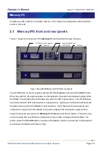
Figure 1 shows the front panel of the
Mercury
iPS and identifies the main features.
Figure 1 MercuryiPS-M (Master) and iPS-S (Slave) front panels
The On/Off button on the front panel switches the iPS-M (Master) into/out of STANDBY mode.
When the switch is off, electrical power is still supplied to the switch-mode power supply inside
the iPS-M. The On/Off button illuminates blue when the iPS is powered up. The iPS-S (Slave)
has a blue indicator LED to show when it is powered up. Any Slave connected to a Master will
be powered-up as part of the Master’s boot sequence. Each Slave will be powered-up and
configured in sequence as the Master boots and configures the total power supply system.
Figure 2
shows the rear panel of a
Mercury
iPS-M (Master) and iPS-S (Slave) . This photo may
not look exactly like your iPS-M as it depends on the number and type of boards fitted. The
picture shows the RS485/Modbus connector of the Master which is used as the communication
bus between the Master and Slave unit(s).
On/Off button and indicator
Ambient light sensor
LCD display
Ammeter
Voltmeter


