


Operator's Manual
Issue 14
/
Mar 2016 / UMC0071
Mercury
iPS
©2016 Oxford Instruments NanoScience. All rights reserved.
Page
131
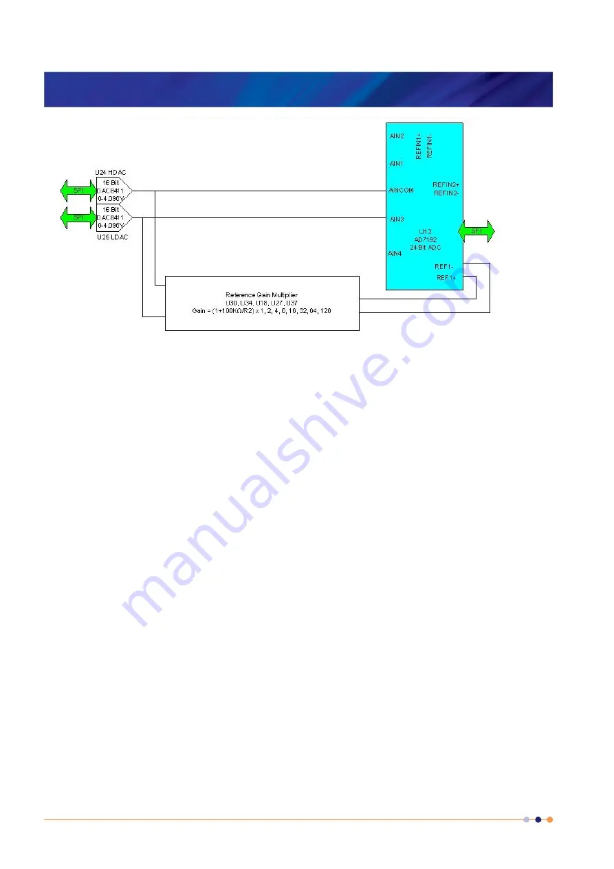
The calibration is performed using a ratiometric circuit configuration. In calibration mode, DACs
U24 and U25 supply a differential calibration voltage to the input of ADC U12. This same
differential voltage is scaled by a reference gain multiplier circuit and supplied to the reference
voltage inputs of U12.
The ADC input has a programmable gain amplifier (PGA) with five gain settings (1, 8, 16, 64
and 128). An autocalibration is performed for each range.
The reference gain multiplier is also programmable with eight gains (1, 2, 4, 8, 16, 32, 64 and
128). Each gain is calibrated at low and high reference voltages (1.2 V and 2.4 V). The exact
gain that is used for calculating sensor resistance is a linear interpolation between these two
values.
It is only necessary to perform this calibration using a positive excitation voltage. The ADC is
operated in chop mode, which eliminates any offsets in the ADC.
Calibration is performed using the highest possible ADC accuracy setting, which is also the
slowest acquisition time. The results are stored in MSP430 flash memory for use during a
measurement whenever a range is changed. Calibration is not performed every time a range is
changed, as this would cause unacceptable measurement delays.


