3 Connection
−
19
−
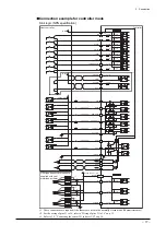
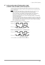
Connection example for controller mode
Source logic (PNP specification)
1 k
Ω
M0
1 k
Ω
4.7 k
Ω
1 k
Ω
4.7 k
Ω
1 k
Ω
4.7 k
Ω
Brown
Black
Blue
Brown
Black
Blue
Brown
Black
Blue
Pink
Pink
Pink
4.7 k
Ω
1 k
Ω
4.7 k
Ω
1 k
Ω
4.7 k
Ω
1 k
Ω
4.7 k
Ω
1 k
Ω
4.7 k
Ω
1 k
Ω
4.7 k
Ω
1 k
Ω
4.7 k
Ω
1 k
Ω
4.7 k
Ω
2.7 k
Ω
2.7 k
Ω
0 V
0 V
24 VDC
24 VDC
0 V
R
0
㸠
10 mA or less
200 mA or less
㸢
R
0
㸠
10 mA or less
R
0
㸠
10 mA or less
R
0
㸠
10 mA or less
R
0
㸠
10 mA or less
11
M5
16
START
7
ACL/CK
8
FREE
9
STOP
10
HOME/PRESET
17
REQ
30
P24-FWD
33
FWD-
32
P24-RVS
36
18
1
RVS-
IN-COM1
IN-COM2
OUT-COM
35
ALM
2
MOVE
3
END/OUTR
4
AREA/OUT0
5
T-UP/OUT1
6
20
21
I/O-GND
19
ASG2
22
23
BSG2
24
25
+LS
13
-LS
14
HOMELS
15
Host controller
Controller
I/O
SENSOR
·
·
·
·
·
·
∗
1
∗
1
∗
1
∗
2
1,11,19
24 VDC 150 mA or less
0 V
ASG2
BSG2
PNP type sensor set
∗
3
∗
3
∗
3
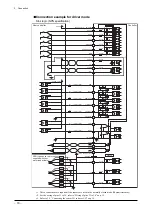
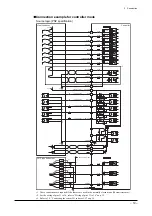
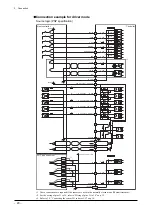
∗1
These connections are required if the sensors are used in the normally closed mode (Photomicrosensor).
∗2
For the wiring of pins 31 to 36, refer to “Wiring of pins 31 to 36” on p.15.
∗3
Refer to 3.5, “Connecting the sensor I/O and user I/O” on p.14.
Summary of Contents for EZ limo ESMC-A2
Page 92: ......


