background image

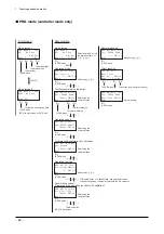
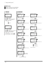
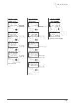
8  Error handling 

 76 


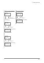
8.4  Checking and clearing the alarm history 

1. 

Press the [F3] key on the first screen of the EXT 
mode. 

2. 

Press the [F2] key to clear the alarm history. 
Press the [F3] key to display the latest alarm history. 

3. 

Press the [

] [

] key to display the history of alarms 

generated to date. Up to ten alarms from the most 
recent one can be displayed. 

' : 6  # N O  0 Q Y
' T T Q T    
2 Q U  1 X G T  ( N Q Y
/ Q F G  % N T  * K U V  # % .

' : 6  # N O  * K U V 
' T T Q T    
0 Q  ' T T Q T
/ Q F G            

' : 6  # N O  * K U V 
' T T Q T    
' / )  ' T T Q T
/ Q F G            

' : 6           + &  
5 G N  0 Q    # E V  0 Q  
2 Q U           O O
/ Q F G  +  1  # N O  & C V C

' : 6  # N O  * K U V 
' T T Q T    
/ C K P  2 Q Y G T  Q H H
/ Q F G            


Summary of Contents for EZ limo ESMC-A2

Page 1: ...underutilized and idle equipment along with credit for buybacks and trade ins Custom engineering so your equipment works exactly as you specify Critical and expedited services Leasing Rentals Demos I...

Page 2: ...C2 OPERATING MANUAL Thank you for purchasing an Oriental Motor product This Operating Manual describes product handling procedures and safety precautions Please read it thoroughly to ensure safe opera...

Page 3: ...ta and alarm code common to the controller and driver modes 36 4 13 Softlimit controller mode only 37 4 14 Speed filter 37 4 15 END signal 37 5 Timing charts 38 5 1 Return to home operation common to...

Page 4: ...e switches on the controller Controller mode driver mode Controller mode The motorized actuator is operated in accordance with the operating data stored in the controller Driver mode The motorized act...

Page 5: ...g environment Ambient temperature 0 to 40 C 32 to 104 F non freezing 25 to 70 C 77 to 158 F non freezing Ambient humidity 85 or less non condensing Altitude Up to 1000 m 3300 ft above sea level Up to...

Page 6: ...ESMC C2 EMI Emission Tests Radiated Emission Test Conducted Emission Test EN 61000 6 4 EN 55011 EN 61000 6 4 EN 55011 EN 55011 EMS Immunity Tests Electrostatic Discharge Immunity Test Radiation Field...

Page 7: ...his connector is used to connect the Emergency stop circuit Motor connector This connector is used to connect the motor cable of the motorized actuator CHARGE LED This LED will be lit when the main po...

Page 8: ...t be changed Resolution maximum operating speed maximum acceleration deceleration motor control settings Note Be sure to confirm that the motorized actuator model shown on the controller key is the sa...

Page 9: ...ttom 20 mm 0 79 in or more Side 20 mm 0 79 in or more Side 20 mm 0 79 in or more 25 mm 0 98 in ESMC K2 165 mm 6 50 in ESMC A2 ESMC C2 180 mm 7 09 in 2 2 How to install the controller Using controller...

Page 10: ...IN rail 1 Pull out the DIN lever 2 Lift the bottom of the controller Note Do not use the mounting holes for the DIN rail mounting plate provided in the back of the controller for any purpose other tha...

Page 11: ...BWZ 4 R C M 601BQZ 4 PHOENIX CONTACT GmbH Co KG PT2 PE S120AC ST PT2 PE S230AC ST Note When measuring dielectric strength of the equipment be sure to remove the surge arrester or the surge arrester ma...

Page 12: ...le Shielded cable Pendant cable Host controller To sensor Grounded panel Ground cable Motor cable Shielded cable Mains filter DC power supply DC power supply A A 3 Shielded cable Battery A Cable clamp...

Page 13: ...ower supply Motorized actuator Emergency stop circuit Controller key Teaching pendant EZT1 or Motor cable Data editing software EZED2 The software comes with a PC interface cable 1 Absolute mode only...

Page 14: ...roller CPU teaching pendant and electromagnetic brake Applicable wire Solid wire AWG16 1 6 mm Stranded wire AWG16 1 25 mm2 Standard strip length 11 mm 0 43 in Pin assignments Emergency stop output ter...

Page 15: ...r I O connector Pin No Signal name Description 1 11 19 IN COM2 Power supply input for sensor 13 LS LS limit sensor input 14 LS LS limit sensor input 15 HOMELS HOME sensor input Note If a photomicrosen...

Page 16: ...peration in the coordinate direction FWD p 31 FP p 32 34 RVS RP 35 RVS RP 36 P24 RVS P24 RP RVS RVS P24 RVS Continuous operation in the coordinate direction RP RP P24 RP Pulse input operation in the c...

Page 17: ...UP OUT1 2 T UP Output when a push motion operation has been completed OUT1 Used to read the current position T UP p 30 OUT1 p 36 20 ASG1 A phase pulse output Open collector 21 BSG1 B phase pulse outpu...

Page 18: ...M5 16 START IN COM1 7 ACL CK 8 FREE 9 STOP 10 HOME PRESET 17 REQ 30 P24 FWD 33 FWD 32 P24 RVS 36 RVS 35 ALM 2 MOVE 3 END OUTR 4 AREA OUT0 5 T UP OUT1 OUT COM 6 1 ASG1 20 BSG1 I O GND 21 19 ASG2 22 23...

Page 19: ...2 8 FREE 9 C OFF 10 HOME PRESET 17 REQ 30 P24 FP 33 FP 32 P24 RP 36 RP 35 ALM 2 MOVE 3 END OUTR 4 TIM OUT0 5 T UP OUT1 OUT COM 6 1 ASG1 20 BSG1 21 19 ASG2 I O GND 22 23 BSG2 24 25 1 11 19 LS 13 LS 14...

Page 20: ...less 11 M5 16 START 7 ACL CK 8 FREE 9 STOP 10 HOME PRESET 17 REQ 30 P24 FWD 33 FWD 32 P24 RVS 36 18 1 RVS IN COM1 IN COM2 OUT COM 35 ALM 2 MOVE 3 END OUTR 4 AREA OUT0 5 T UP OUT1 6 20 21 I O GND 19 A...

Page 21: ...E 9 C OFF 10 HOME PRESET 17 REQ 30 P24 FP 33 FP 32 P24 RP 36 18 RP IN COM1 OUT COM 35 ALM 2 1 MOVE 3 END OUTR 4 TIM OUT0 5 T UP OUT1 6 20 21 I O COM 19 ASG2 22 23 BSG2 24 IN COM2 25 LS 13 LS 14 HOMELS...

Page 22: ...so may cause the overcurrent protection fuse in the teaching pendant to blow in which case the emergency stop can no longer be reset Provide a measure on the machine side so that the machine will ope...

Page 23: ...y input terminal Power supply input terminal PENDANT PC Pendant switch Emergency stop button SB3 Emergency stop cancellation button SB1 Emergency stop button SB2 Relay KA1 FU1 FU2 6 5 EMG L N 0 V 0 V...

Page 24: ...ut terminal PENDANT PC Pendant switch Emergency stop button SB3 FU1 FU2 6 5 EMG L N 0 V AC ESMC A2 ESMC C2 FU1 FU2 ESMC K2 24 VDC 24 VDC 0 V Emergency stop output terminal Note When the emergency stop...

Page 25: ...o the controller before removing the battery ESMC A2 or ESMC C2 from the controller Pin assignments of battery connector Battery power ground Battery power input Note The product is shipped with an un...

Page 26: ...EZC series and EZA series actuator In the sensor less mode the table will move to the mechanical hard stop position Push motion 1 Sensor less return to home operation is performed at the starting spee...

Page 27: ...ELS becomes the home Acceleration deceleration operation is performed at the operating speed of return HVr HOMELS LS LS HOMELS LS LS HOMELS LS LS HOMELS LS LS HOMELS LS LS HOMELS LS LS HOMELS LS LS HO...

Page 28: ...erformed sequentially using multiple operating data starting from the selected data Setting data Operating data Positioning mode distance direction operating speed operating function acceleration dece...

Page 29: ...to the acceleration deceleration No set for the first operating data set that has been linked In the fourth line of operation data set Single motion or Push motion in the operation function field If...

Page 30: ...Deceleration No Operating function 1 Abs 100 mm 3 94 in 60 mm s 2 36 in s 0 Linked motion 2 Abs 0 mm 0 in 60 mm s 2 36 in s 3 Single motion 100 mm 3 94 in 100 mm 3 94 in 0 mm 0 in Home position The a...

Page 31: ...sly subjected to pressure is called push motion operation This operation can be performed only when push motion is selected as the operating function When the actuator contacts the load during positio...

Page 32: ...mm s 1 18 in s 0 2 50 mm s 1 97 in s 3 6 mm s 0 24 in s 60 mm s 2 36 in s 3 10 mm s 0 39 in s 1 4 Not set 2 Execution example 1 M0 to M5 input FWD input RVS input Operating speed 30 mm s 1 18 in s Op...

Page 33: ...es according to the equipment connected to the controller Note Pulse input is implemented based on the negative logic Pulse input mode I O parameters Pulse input switching 1P 2P selection Waveform ima...

Page 34: ...e frequency corresponding to the maximum speed used by your equipment When using the line driver output connect a terminating resistance of 150 between the line receiver inputs When using the open col...

Page 35: ...e used when the operating speed is 5 mm s 0 2 in s or below or 0 5 mm s 0 02 in s or below if the SPRM4G PWAM8J and ESR series is connected Pulse input TIM output Rotor revolution of 7 2 1 24 48 Opera...

Page 36: ...p Deceleration stop Immediate stop current OFF not excited electromagnetic brake actuated This setting cannot be selected by the HMSTOP input Deceleration stop current OFF not excited electromagnetic...

Page 37: ...45 decimal 0000 0000 0000 0000 0011 0000 0011 1001 12345 100 123 45 mm 4 860 in Current positioning data Status 8 bits These bits indicate the controller status Different information is assigned to ea...

Page 38: ...eration will also be reduced which will consequently allow the motorized actuator to operate smoothly However the greater the filter time constant the lower the operating command response becomes Ther...

Page 39: ...he following two methods to turn on the HOME input Hold the HOME input in the ON position for more than 4ms or hold the HOME input in the ON position until the MOVE output turns ON 2 The time after an...

Page 40: ...ime after an operation ends until the END output turns ON varies depending on the load and operating speed 5 2 Positioning operation controller mode only START input MOVE output END output 6 ms or les...

Page 41: ...OFF 15 OFF OFF ON ON ON ON 47 ON OFF ON ON ON ON 16 OFF ON OFF OFF OFF OFF 48 ON ON OFF OFF OFF OFF 17 OFF ON OFF OFF OFF ON 49 ON ON OFF OFF OFF ON 18 OFF ON OFF OFF ON OFF 50 ON ON OFF OFF ON OFF 1...

Page 42: ...ating speed 1 pulse input mode ON OFF ON OFF ON OFF ON OFF FP input RP input MOVE output END output cordinate direction cordinate direction 2 ms or less 3 ms or less 2 ms or less 3 ms or less The time...

Page 43: ...d ON until the motor stops and the time after the MOVE output turns OFF until the END output turns ON vary depending on the load and operating speed Deceleration stop STOP input HMSTOP input START inp...

Page 44: ...he MOVE output turns OFF until the END output turns ON vary depending on the load and operating speed Deceleration stop electromagnetic brake actuation STOP input START input MOVE output END output Mo...

Page 45: ...magnetic brake Release Motor is excited motor is not excited C OFF Input driver mode only C OFF input Motor excitation FP or RP input 100 ms or less 100 ms or more Delay when the motor is not excited...

Page 46: ...ON 1 Turn the REQ input ON 2 When the OUTR output turns ON turn the CK input ON When the OUTR output turns OFF save the statuses of OUT0 and OUT1 outputs to the host controller 3 Turn the CK input OF...

Page 47: ...gives a brief explanation of the starting procedure from turning on the controller power to actually operating the actuator 1 Wire each connector on the controller 2 Confirm that the motorized actuat...

Page 48: ...oss alarm Err33 should no longer generate 7 Set data using the teaching pendant EZT1 or data editing software EZED2 8 Perform return to home operation Timing chart at power on controller mode only STA...

Page 49: ...NT key Once you have set the language this screen will no longer appear the next time you start the controller The following screens assume that English has been selected 3 Press the F1 key three time...

Page 50: ...ENT key 3 Select Abs using the keys 4 Press the ENT key 5 Enter 45 00 using the numerical keys 6 Press the ENT key 6 5 G N E V 2 Q U O O Q F G 1 N O C V C 2 4 C V C 0 Q F C V C 0 6 F K V Q F G N T P U...

Page 51: ...e operating data is set to operation No 1 2 4 1 2 W P E W P E 5 K P I N G Q V K Q P 0 6 5 G V Q F G 2 4 1 2 W P E W P E 5 K P I N G Q V K Q P 0 6 5 G V Q F G 2 4 5 R G G F 5 R F O O U M G U 0 6 5 G V...

Page 52: ...e 2 Press the F4 key to select test operation 3 Press the START key to execute operating data No 1 Press the STOP key to stop the operation 2 4 C V C 0 Q F C V C 0 6 F K V Q F G N T P U G N 6 5 6 5 G...

Page 53: ...only This mode is used to set positioning operating data 2 4 C V C 0 Q F C V C 0 6 F K V Q F G N T P U G N F3 key Insert operating data ENT key Edit operating data Operating mode Push motion current...

Page 54: ...rate Clearing inserting and deleting data 1 Press one of F2 to F4 keys on the first screen of the PRG mode 2 Press the F3 key on each screen to perform the desired operation Clearing data No data is s...

Page 55: ...V C 0 Q F C V C Q F G E N T 2 4 C V C 0 Q F C V C 0 6 F K V Q F G N T P U G N Execute First screen of the PRG mode 7 3 Initializing the parameters Reset all parameters to their default values 1 On th...

Page 56: ...tor 5 After the position has been confirmed press the ENT key The current position is set to the operating data 2 4 0 Q 4 O V P E 2 Q U O O 0 6 5 G V Q F G 2 4 2 Q U P E 2 Q U O O M G U 0 6 5 G V Q F...

Page 57: ...ress the F3 key to turn off the excitation of the motorized actuator 6 Move the actuator s moving part manually to change the position 7 After the position has been confirmed press the ENT key The cur...

Page 58: ...First screen of the EXT mode Example of controller mode Description of I O monitor screen 6 1 P K V Q F G Bit image corresponding to data number 1 ON 0 OFF ON OFF The signals are aligned in the follo...

Page 59: ...I O check 2 Press one of F2 to F4 keys Use the keys to move through the items on the applicable check screen selected by pressing one of F2 to F4 keys Input signals Input signals can be monitored ON...

Page 60: ...ome operation 6 5 6 5 G N G E V Q F G 1 P W 1 R T 6 5 6 1 R T 2 Q U O O M G 5 6 4 6 Q F G 2 4 1 6 5 6 P W P W 1 R T 2 Q U O O Q F G 2 4 1 Manual operation Operate the motorized actuator Perform return...

Page 61: ...I W C I G P I N K U J 0 6 5 G V Q F G Select using Language setting F1 To PAR mode Current position display 1 I O monitor First screen and language setting I O monitor Current position display 2 Curr...

Page 62: ...0 Q T T Q T Q F G C C D C D C D C D C D Current alarm information Alarm history Clear alarm history Data checking Alarm monitor F1 to PRG mode F1 to PRG mode F1 to PRG mode F1 to PRG mode to PAR mode...

Page 63: ...he numerical keys If SingleMotion or LinkedMotion has been selected as the operating mode the display returns to the No selection No selection 1 No selection Operating mode No selection 2 Position num...

Page 64: ...C V C N G C T K P I C N N F C V C 9 C K V H Q T C O Q O G P V Data clear All operating data clear Data insertion Screen displayed during the processing Screen displayed during the processing Data del...

Page 65: ...g To pulse input mode switching Enter using the numerical keys No selection 1 No selection 2 Stop action Stop logic C OFF logic PRESET position setting HOME PRESET switching LS detection enable disabl...

Page 66: ...direction Home offset Return mode Operating speed of return Starting speed of return Initialize parameters To return direction Screen displayed during the processing Select using Select using Enter us...

Page 67: ...l keys F1 to TST mode F1 to TST mode 2 4 5 R F E E E E O U M G U 0 6 5 G V Q F G 2 4 5 R F G E G E O U M G U 0 6 5 G V Q F G Acceleration rate No 2 Deceleration rate No 2 Enter using the numerical key...

Page 68: ...G U 0 6 5 G V Q F G 2 4 Q O T G C T G C O O M G U 0 6 5 G V Q F G C D Common parameters Softlimit Upper softlimit Lower softlimit Area 1 Area 2 Coordinate setting Common parameters Coordinate setting...

Page 69: ...1 Q F G 2 W U J 6 5 6 1 1 W V N N 1 7 6 Q F G I O checking I O selection Input check First screen Item selection Item selection Output check Encoder pulse output check To In1 To Out1 D First screen F1...

Page 70: ...4 1 C C I O checking I O selection Input check Output check Manual operation Positioning operation To In1 To Out1 Encoder pulse output check F1 F2 F3 F4 ESC to first screen ESC to I O selection ESC t...

Page 71: ...ON Turn the STOP input OFF An operating data number for which no operating data has been set is selected Select an operating data number for which operating data has been set and then turn the START...

Page 72: ...number of times the ALARM LED blinks When an alarm occurs the ALARM LED will repeat a certain blink pattern as shown below the LED blinks three times in this example 1 2 3 1 2 3 0 2 s 0 2 s 1 2 s 2 If...

Page 73: ...ver Voltage 1 The DC voltage of the main circuit is too high Reduce the load or decrease the acceleration Valid Main power OFF detection Err23 Main Power Off 1 Main power OFF detection Check to see if...

Page 74: ...e sensor enable mode Reset the alarm and then check the logic of the installed sensors and the logic setting in the LS logic setting parameter Valid LS reverse connection error Err61 LS Rev Error 2 Th...

Page 75: ...erating Turn off the power and check the motor cable and its connection to the controller and then cycle the power Invalid Controller key communication error Err2A Actuator No Connect 1 A communicatio...

Page 76: ...data editing software Invalid 8 3 Teaching pendant errors If a communication error occurs between the teaching pendant and controller the corresponding message will be displayed and the screen will t...

Page 77: ...display the latest alarm history 3 Press the key to display the history of alarms generated to date Up to ten alarms from the most recent one can be displayed 6 N O 0 Q Y T T Q T 2 Q U 1 X G T N Q Y...

Page 78: ...y specification ESRM3 ESRM4 ESRM5 ESRM6 ESRM8 ESMC K2 24 VDC 1 0 A 1 1 A 1 7 A 4 0 A ESMC A2 Single phase 100 115 V 3 0 A 5 0 A ESMC C2 Single phase 200 230 V 2 1 A 3 0 A SPV series Controller model P...

Page 79: ...arameters For example acceleration deceleration No 0 indicates a combination of acceleration No 0 and deceleration No 0 p 27 Operating function Func Single motion Operation is performed based on a sel...

Page 80: ...ommands The greater the value set in this parameter the more gradual the speed change becomes at standstill and consequently the smaller the vibration damping becomes at standstill However positioning...

Page 81: ...eters Display Description Reference Softlimit enable disable Soft Lim Set this parameter to Enable if soft limits are to be used p 37 Upper softlimit Lim Set the upper soft limit in the direction p 37...

Page 82: ...rn direction To Motor Opp Motor To Motor Home offset 83886 08 to 83886 07 mm 3302 60 to 3302 60 in 0 00 Return method Push1 Push2 2 2 sensor mode 3 3 sensor mode Push1 Starting speed of return Push1 P...

Page 83: ...004 to 7 87 in s For the SPFM8C DC input type 0 01 to 150 mm s 0 0004 to 5 91 in s SPFM6 SPFM8C 5 00 mm s 0 20 in s SPFM8B 10 00 mm s 0 39 in s Home parameters Operating speed of return 0 01 mm s to m...

Page 84: ...O set HOME PRESET switching HOME PRESET HOME PRESET position SPRM4 8388 608 to 8388 607 mm 330 260 to330 260 in SPRM6 SPRM8 83886 08 to 83886 07 mm 3302 60 to 3302 60 in SPRM4 0 000 SPRM6 SPRM8 0 00 P...

Page 85: ...0 328 ft s2 SPRM6 SPRM8 0 45 m s2 1 476 ft s2 Speed parameters Common operating speed SPRM4 0 001 to 50 mm s 0 00004 to 1 97 in s For the SPRM6 DC input type 0 01 to 100 mm s 0 0004 to 3 94 in s For t...

Page 86: ...n 0 001 to 200 mm s 0 00004 to 7 87 in s ESRM3 only 0 001 to 100 mm s 0 00004 to 3 94 in s 6 000 mm s 0 24 in s ESRM3 only 2 500 mm s 0 098 in s Home parameters Operating speed of return 0 001 mm s to...

Page 87: ...3302 60 in 0 00 Return method 2 2 sensor mode 3 3 sensor mode 3 Starting speed of return 0 01 to 200 mm s 0 0004 to 7 87 in s SPVM6 35 00 mm s 1 38 in s SPVM8 45 00 mm s 1 77 in s Home parameters Ope...

Page 88: ...logic NO set NC set NO set HOME logic NO set NC set NO set I O PARAMETERS Overtravel Imd stop Dec stop Imd stop Operating current 0 to 100 100 Standstill current PWAM6 0 to 60 PWAM8 0 to 70 PWAM6 60 P...

Page 89: ...886 08 to 83886 07 mm 3302 60 to 3302 60 in PWAM8 8388 608 to 8388 607 mm 330 260 to330 260 in 1 00 mm 0 04 in Area 1 PWAM6 83886 08 to 83886 07 mm 3302 60 to 3302 60 in PWAM8 8388 608 to 8388 607 mm...

Page 90: ...turn direction To Motor Opp Motor To Motor Home offset 83886 08 to 83886 07 mm 3302 60 to 3302 60 in 0 00 Return method Push1 Push2 2 2 sensor mode 3 3 sensor mode Push1 Starting speed of return Push1...

Page 91: ...turn direction To Motor Opp Motor To Motor Home offset 83886 08 to 83886 07 mm 3302 60 to 3302 60 in 0 00 Return method Push1 Push2 2 2 sensor mode 3 3 sensor mode Push1 Starting speed of return Push1...

Page 92: ......

Page 93: ...their respective companies and are hereby acknowledged The third party products mentioned in this manual are recommended products and references to their names shall not be construed as any form of p...

Page 94: ...uipment Have surplus equipment taking up shelf space We ll give it a new home Learn more Visit us at artisantg com for more info on price quotes drivers technical specifications manuals and documentat...

Reviews: