45
Fe
a
tu
re
s
H
o
w to R
e
a
d
S
p
e
cif
ications
T
a
ble
Sy
st
e
m
Configur
a
tion
Specifications and
Dimensions
Stan
d
a
rd
T
y
p
e
Specifications and
Dimensions
Gu
id
e
T
y
pe
Specifications and
Dimensions
Ta
b
le
Ty
p
e
Gen
e
ra
l
S
p
e
cif
ications
Specifications, Dimensions,
Connections
Dri
ve
r
Combination
List
A
c
ces
s
or
ies
Sele
c
tion
ca
lculation
●
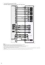
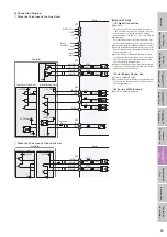
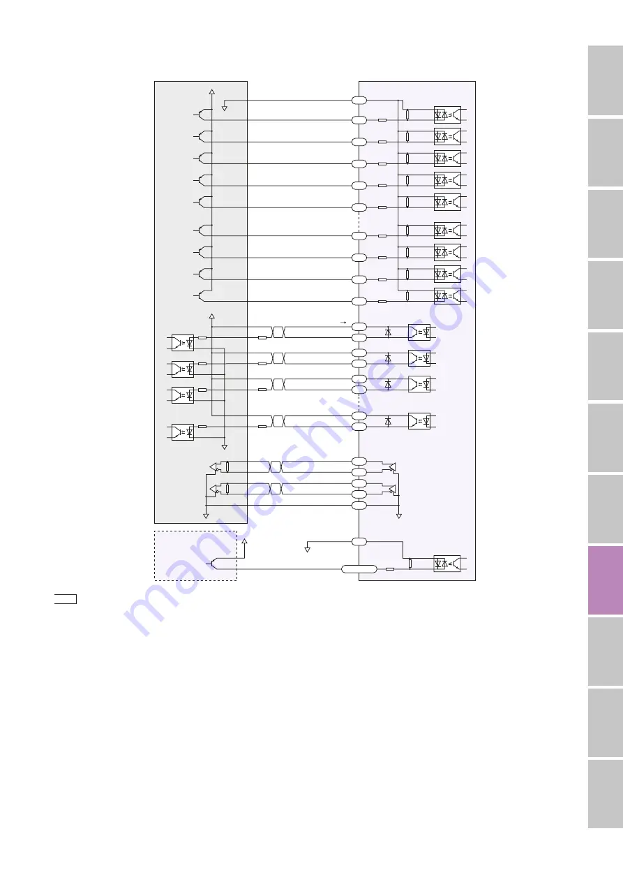
Connection Diagram for Connection with Current Source Output Circuit
+
LS,
−
LS, HOMES, SLIT
1 k
Ω
1 k
Ω
1 k
Ω
1 k
Ω
1 k
Ω
1 k
Ω
1 k
Ω
1 k
Ω
1 k
Ω
1 k
Ω
4.4 k
Ω
4.4 k
Ω
4.4 k
Ω
4.4 k
Ω
4.4 k
Ω
4.4 k
Ω
4.4 k
Ω
4.4 k
Ω
4.4 k
Ω
4.4 k
Ω
GND
DIR-OUT
PLS-OUT
0 V
✽
0 V
R
0
R
0
R
0
R
0
+
24 VDC
0 V
OUT4
OUT1
ALM
MOVE
RVS
FWD
HOME/P-PRESET
M5
M0
STOP
AWO
ALM-RST
START
IN-COM1
IN-COM0
+
24 VDC
0 V
0 V
B19
B18
B17
B16
B15
A1
A2
A3
A4
A20
A15
∼
A18
A5
A11
A6
A12
A13
B12
B11
B6
B5
B4
B3
B2
B1
A14
Driver
Programmable Controller
Sensor
20 mA
max.
+
24 VDC
max.
26C31
or Equivalent
Notes
●
Use the included cable with connector for the I/O signal cable and keep the wiring distance as short as possible.
●
Use 24 VDC for the input signals. Using voltage exceeding the specifications can break elements.
●
Use 24 VDC max. and current of 20 mA max. for the output signals. Using voltage exceeding the specifications can break elements.
Check the specifications for the connected equipment. If the current exceeds 20 mA, connect the external resistor R
0
.
●
Connect a terminating resistor of 100
Ω
min. between the line receiver inputs.
●
Provide a distance of 100 mm min. between the signal lines and power lines (power supply lines, actuator lines). Do not run the signal lines in the same piping as power lines or bundle them with
power lines.
●
If noise generated by the actuator cable or power supply cable causes a problem with the specific wiring or layout, shield the cable or use ferrite cores.
✽
This is common with the CN1 ground (not insulated).


