Fe
a
tu
re
s
H
o
w to R
e
a
d
S
p
e
cif
ications
T
a
ble
Sy
st
e
m
Configur
a
tion
Specifications and
Dimensions
Stan
d
a
rd
T
y
p
e
Specifications and
Dimensions
Gu
id
e
T
y
pe
Specifications and
Dimensions
Ta
b
le
Ty
p
e
Gen
e
ra
l
S
p
e
cif
ications
Specifications, Dimensions,
Connections
Dri
ve
r
Combination
List
A
c
ces
s
or
ies
Sele
c
tion
ca
lculation
13
■
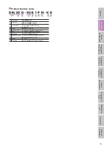
Product Number Code
①
②
③
④ ⑤ ⑥ ⑦
⑨
⑧
⑩
DRL 20 G - 02 B 1 P N - K D
①
Series Name
DRL
:
DRL
Series
②
Frame Size
20
:
□
20 mm
28
:
□
28 mm
42
:
□
42 mm
60
:
□
60 mm
③
Configuration
Blank: Standard Type
G
: Guide Type
V
: Table Type
④
Stroke
02
∼
10
: 25
∼
100 mm
⑤
Ball Screw Type
A
: Rolled Ball Screw
B
: Ground Ball Screw
⑥
Lead
1
: 1 mm
2
: 2 mm
4
: 4 mm
8
: 8 mm
⑦
Motor Type
P
: Standard
M
: High Resolution
⑧
Additional Function
Blank: No Function
N
: Adjustment Knob Type
M
: Electromagnetic Brake Type
⑨
Voltage
K
: 24 VDC
⑩
Driver Type
B
: Pulse Input
D
:
Built-In Controller

