43
Fe
a
tu
re
s
H
o
w to R
e
a
d
S
p
e
cif
ications
T
a
ble
Sy
st
e
m
Configur
a
tion
Specifications and
Dimensions
Stan
d
a
rd
T
y
p
e
Specifications and
Dimensions
Gu
id
e
T
y
pe
Specifications and
Dimensions
Ta
b
le
Ty
p
e
Gen
e
ra
l
S
p
e
cif
ications
Specifications, Dimensions,
Connections
Dri
ve
r
Combination
List
A
c
ces
s
or
ies
Sele
c
tion
ca
lculation
●
Connection Diagram
◇
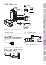
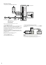
Connections with Peripheral Equipment
GND
+
24 V
FG
Included with product.
Sold separately as accessories.
Connect to the driver with the communications cable
for data setting software
CC05IF-USB
(sold separately).
or
Programmable Controller
or Master Equipment
Connect when controlling
with RS-485
communications.
Programmable Controller
Actuator
Connected to CN6
or
CN7
Connected to
CN3
Connected to
CN2
✽
2
Connected to
CN4
✽
1
DC Power Supply
Noise Filter
Use as protection against
noise.
This is effective for reducing
noise generated from the
power supply and driver.
AC
Power Supply
Control Module
OPX-2A
(Sold separately)
Data Setting Software
MEXE02
✽
1 When the product or the driver is purchased, it comes with a 0.6 m connection cable.
✽
2 When the product or the driver is purchased, it comes with a 1 m connection cable.
●
Keep the wiring distance between the actuator and driver to 10 m max..
◇
Power Supply Connection
Use the included connector for CN1 to connect the power cable
(AWG22: 0.3 mm
2
) to the driver's power connector (CN1).
Connecting the DC power-supply input with the polarity reversed
would damage the driver (circuits). Make sure that the polarity is
correct before turning power on.
Provide a power supply that can supply adequate input current.
If the power supply capacity is inadequate, abnormalities such as
the following occur.
●
The actuator does not operate normally in high-speed operation.
●
The actuator does not accelerate or decelerate as set.
FG
GND
24 VDC
Power Supply
Connector for CN1
(Included)
Power Connector (
CN1
)
◇
Actuator Connection
Connect using the included connection cable (for actuator connector,
CN4).
The terminals and connectors required for connecting the motor
leads and the connection cable are not included.
For motor lead extension, use a wire of AWG22 (0.3 mm
2
) min.
Motor Leads
or
Connection Cable (Included)
Connection Cable
(Included)
Actuator
Connector (
CN4
)
Blue
Red
Orange
Green
Black
Blue
Red
Orange
Green
Black
◇
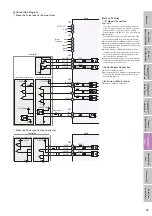
Connecting the Electromagnetic Brake
Use power supplies of 24 VDC±5%
✽
, 0.25 A min. (for the
DRL42
,
0.08 A min.)
Surge
Suppressor
(Included)
Switch
Black/White
Red/White
24 VDC
±
5%
✽
0.25 A
min.
(
DRL42
:
0.08 A
min.)
Motor Leads
Electromagnetic
Brake Leads
✽
If the wiring distance is extended by 20 m or more, the specification becomes 24 VDC
±
4%.
Notes
●
Applying voltage exceeding the specifications causes actuator failure.
●
To protect the switch contacts and prevent noise, always connect a surge suppressor.
(The surge suppressor is included with electromagnetic brake motors.)


