39
Fe
a
tu
re
s
H
o
w to R
e
a
d
S
p
e
cif
ications
T
a
ble
Sy
st
e
m
Configur
a
tion
Specifications and
Dimensions
Stan
d
a
rd
T
y
p
e
Specifications and
Dimensions
Gu
id
e
T
y
pe
Specifications and
Dimensions
Ta
b
le
Ty
p
e
Gen
e
ra
l
S
p
e
cif
ications
Specifications, Dimensions,
Connections
Dri
ve
r
Combination
List
A
c
ces
s
or
ies
Sele
c
tion
ca
lculation
■
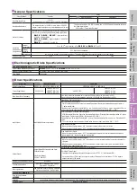
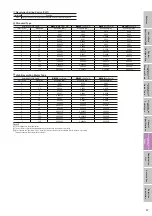
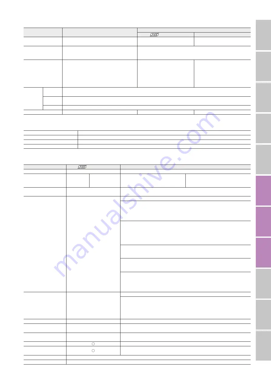
General Specifications
Specifications
Actuator
Driver
Built-in Controller
Pulse Input
Heat-Resistant Class
130 (B)
[Recognized as 105 (A) under the UL and CSA Standards.]
−
−
Insulation Resistance
The measured value is 100 M
Ω
or more when a 500 VDC
megger is applied between the motor windings and the case.
The measured value is 100 M
Ω
or more when a 500 VDC megger is applied between
the following locations:
·
FG Terminal – Power Input Terminal
Dielectric Voltage
No abnormality is found between the motor windings and
the case for 1 minute even with the following application:
·
DRL20
□
,
DRL28
□
,
DRL42
□
(high resolution):
0.5 kVAC, 50 Hz or 60 Hz
·
DRL42
□
,
DRL60
□
(high resolution): 1.0 kVAC, 50
Hz or 60 Hz
·
DRL60
□
: 1.5 kVAC 50 Hz or 60 Hz
−
−
Operating
Environment
(In operation)
Ambient
Temperature
0 to
+
40˚C
✽
(non-freezing)
✽
For
DRL20V
and
DRL28V
,
5 to 40˚C.
Ambient
Humidity
85% Max. (Non-condensing)
Atmosphere
Use in an area without corrosive gases and dust. The product should not be exposed to water, oil or other liquids.
Degree of Protection
IP00
IP10
IP20
■
Electromagnetic Brake Specifications
Type of Electromagnetic Brake
Power Off Activated Type
Power Supply Input Voltage/Current
DRL42
: 24 VDC
±
5% 0.08 A
DRL60
: 24 VDC
±
5% 0.25 A
Brake Activation/Release Time
Activation Time: 20 ms Release Time: 30 ms
Time Rating
Continuous
■
Driver Specifications
Driver Type
Built-in Controller
Pulse Input
Driver Product Name
LRD503-KD
,
LRD507-KD
,
LRD514-KD
LRD503-K
,
LRD507-K
,
LRD514-K
Power-Supply Input
24 VDC
±
10%
LRD503-KD
: 0.7 A
LRD507-KD
: 1.4 A
LRD514-KD
: 2.5 A
24 VDC
±
10%
LRD503-K
: 0.7 A
LRD507-K
: 1.4 A
LRD514-K
: 2.5 A
Max. Input Pulse Frequency
−
Line driver output by programmable controller: 500 kHz (When the pulse duty is 50%)
Open collector output by programmable controller: 250 kHz (When the pulse duty is 50%)
Input Signal
Input Mode: Photocoupler Input
Input Mode: Photocoupler Input
CW Pulse Signal (Pulse signal)
CW (Forward) Direction Operation Command Pulse Signal (Operation command pulse signal when in
1-pulse input mode)
Negative Logic Pulse Input, Pulse Width 1
μ
s min., Pulse Rise and Fall Time 2
μ
s max., Pulse Duty 50% max.
The screw shaft moves one step forward when the pulse input is switched "ON"
➝
"OFF."
CCW Pulse Signal (Traveling direction signal)
CCW (Backward) Direction Operation Command Pulse Signal (Traveling direction signal when in 1-pulse
input mode - Photocoupler ON: CW, Photocoupler OFF: CCW)
Negative Logic Pulse Input, Pulse Width 1
μ
s min., Pulse Rise and Fall Time 2
μ
s max., Pulse Duty 50%
max.
The screw shaft moves one step backward when the pulse input is switched "ON"
➝
"OFF."
All Windings Off Signal
When the signal is photocoupler "ON", the output current to the actuator is cut off.
When the signal is photocoupler "OFF", the output current is supplied to the actuator.
Step Angle Select Signal
When the signal is photocoupler "OFF", the step angle setting switch is selected; when the signal is
photocoupler "ON", the basic step angle is selected.
Automatic Current Cutback Release Signal
When the signal is photocoupler "ON", the automatic current cutback function for actuator standstill is
released.
When the signal is photocoupler "OFF", the automatic current cutback function is activated after the
actuator stops (approximately 100 ms).
Output Signal
Output Mode: Photocoupler and Open-
Collector Output
Line Driver Output
PLS-OUT, DIR-OUT
Output Mode: Photocoupler and Open-Collector Output
Excitation Timing Signal
This signal is output when the excitation sequence is at STEP "0". (Photocoupler: ON)
For a resolution of 1: The signal is output once every 10 pulses. For a resolution of 10: The signal is
output once every 100 pulses.
Number of Positioning Data Sets
63 Points
−
Positioning Operation
One-Shot, Linked Operation, Linked
Operation 2, Sequential
−
Other Operations
Jog Operation, Return-to-Home Operation,
Continuous Operation, Test Operation
−
Control Module
OPX-2A
−
Data Setting Software
MEXE02
−
Function
Smooth Drive, Automatic Current Cutback, Step Angle Select, Pulse Input Mode Switch (Pulse input only), All Windings Off, Excitation Timing
Cooling Method
Natural Cooling Method

