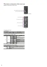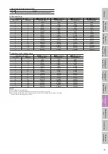
49
Fe
a
tu
re
s
H
o
w to R
e
a
d
S
p
e
cif
ications
T
a
ble
Sy
st
e
m
Configur
a
tion
Specifications and
Dimensions
Stan
d
a
rd
T
y
p
e
Specifications and
Dimensions
Gu
id
e
T
y
pe
Specifications and
Dimensions
Ta
b
le
Ty
p
e
Gen
e
ra
l
S
p
e
cif
ications
Specifications, Dimensions,
Connections
Dri
ve
r
Combination
List
A
c
ces
s
or
ies
Sele
c
tion
ca
lculation
●
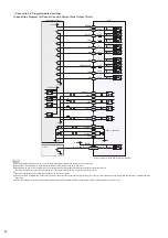
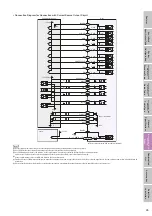
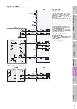
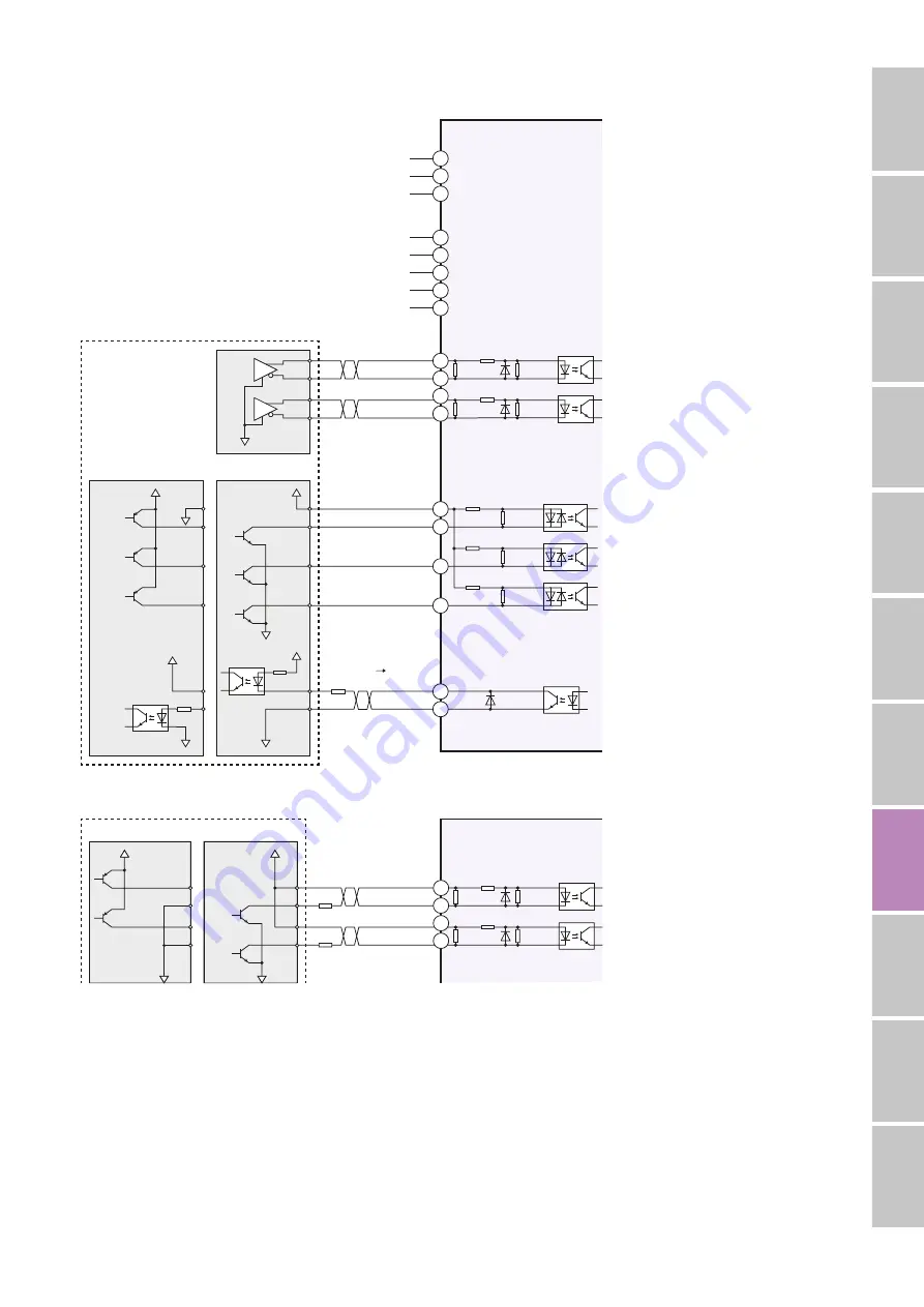
Connection Diagram
◇
When the Pulse Input is the Line Driver
R
0
0 V
0 V
0 V
0 V
GND
24 VDC
±
10%
FG
CW(PLS)
+
CW(PLS)
−
CCW(DIR)
+
CCW(DIR)
−
IN-COM
AWO
CS
TIM+
TIM-
CN3
CN3
CN3
CN1
5
4
3
2
1
4
3
2
1
7
6
10
9
5
8
3
2
1
CN2
200
Ω
200
Ω
3 k
Ω
10 k
Ω
10 k
Ω
2.2 k
Ω
2.2 k
Ω
10 k
Ω
10 k
Ω
10 k
Ω
ACDOFF
3 k
Ω
3 k
Ω
0 V
5
∼
24 VDC
5
∼
24 VDC
Driver
Red
Blue
Motor
Lead Wire
Green
Black
Orange
Current Sink Output Circuit
Current Source Output Circuit
Controller
30 VDC
max.
30 VDC
max.
10 mA
max.
[Note on Wiring]
◇
I/O Signal Connection
●
Input Signal
The external resistor is not needed when the voltage is
5 VDC. If voltage exceeding 5 VDC is applied, connect an
external resistor R
1
so that the current is 7 to 20 mA.
Example) When V
0
is 24 VDC, R
1
: 1.5 to 2.2 k
Ω
, 0.5 W min.
●
Output Signal
Check the specifications of the connected devices. If the
current exceeds 10 mA, connect the external resistor R
0
.
●
Use a twisted-pair wire of AWG26 to 20 (0.14 to 0.5 mm2).
●
Since the maximum transmissible frequency drops as the
pulse line becomes longer, keep the wiring length as short
as possible (within 2 m).
●
Provide a distance of 100 mm min. between the signal
lines and power lines (power supply lines, actuator lines).
Do not run the signal lines in the same piping as power
lines or bundle them with power lines.
●
If noise generated by the actuator cable or power supply
cable causes a problem with the specific wiring or layout,
shield the cable or use ferrite cores.
◇
Power Supply Connection
●
Use a wire of AWG22 (0.3 mm2).
●
Incorrect polarities of the DC power-supply input will lead
to driver damage. Make sure that the polarity is correct
before turning power on.
◇
Extension of Motor Lead
●
Use a wire of AWG22 (0.3 mm2) min.
◇
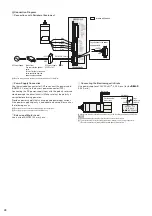
When the Pulse Input is Open Collector
R
1
R
1
0 V
0 V
5
∼
24 VDC
5
∼
24 VDC
CW(PLS)
+
CW(PLS)
−
CCW(DIR)
+
CCW(DIR)
−
CN3
4
3
2
1
200
Ω
200
Ω
10 k
Ω
10 k
Ω
2.2 k
Ω
2.2 k
Ω
Driver
Controller
Current Sink Output Circuit
Current Source Output Circuit

