12
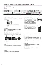
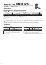
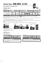
How to Read the Specifications Table
■
For
DRL20V
Table Type
●
Actuator
①
Repetitive Positioning
Accuracy [mm]
±
0.003
Lost Motion [mm]
Ground Ball Screw: 0.02
③
Max. Load Moment [N
·
m]
M
P
:0.4 M
Y
:0.4 M
R
:0.8
Traveling Parallelism [mm]
0.03
Product Name
Stroke
Ball Screw Type
Lead
Resolution
✽
1
(Resolution of 1)
Max. Transportable
Mass [kg]
Max. Thrust
Force
✽
3
Max. Holding
Force
✽
4
Max.
Speed
✽
5
Max.
Acceleration
[mm]
[mm]
[mm]
Horizontal
Vertical
✽
2
[N]
[N]
[mm/s]
[m/s
2
]
DRL20V-02B1P
■
-K
■
25
Ground 1
0.002
1.5
1.5
15
15
20
0.2
②
④
⑤
⑥
⑦
⑧
⑨
⑩
⑪
⑫
①
Repetitive Positioning Accuracy
A value indicating the amount of error that is generated when
positioning is performed repeatedly to the same position in the
same direction.
①
Repetitive positioning accuracy is measured at the tip of the
guide.
②
Repetitive positioning accuracy is measured on the
linear guide.
If footnote
①
or
②
is not indicated, then the accuracy values
are identical.
②
Lost Motion
Positioning error that occurs when positioning to a specific
point in the opposite direction.
③
Max. Load Moment
Force that tries to rotate the guide is applied when the center
(gravity) of the actuator guide and load have an offset. This
refers to the maximum force that can be applied to the guide.
M
R
M
P
M
Y
Support Point
Support Point
Support Point
④
Traveling Parallelism
Runout in the height between the actuator table installation
surface and the top surface of the table.
⑤
Stroke
The maximum distance the load can be pushed and pulled.
⑥
Lead
Distance the screw shaft moves in the linear direction in one
motor rotation.
⑦
Resolution
Distance the screw shaft moves with one pulse input.
⑧
Max. Transportable Mass
●
Horizontal Direction
This is the maximum mass that can be
moved under rated conditions when the
actuator is used in the horizontal direction.
For the standard configuration the
thrust force is reduced by the amount of
frictional resistance of the sliding surface
and the mass of a guide, therefore the
value cannot be shown.
Figure A
●
Vertical Direction
This is the maximum mass that can be
moved under rated conditions when the
actuator is used in the vertical direction.
Figure B
⑨
Max. Thrust Force
Maximum thrust force at constant-speed operation with no
load to the screw shaft.
⑩
Max. Holding Force
The maximum holding force is the holding force when the
automatic current cutback function is ON (Standstill current:
50%).
The holding force is 0 when the power is OFF. The maximum
holding force for the electromagnetic brake is the same value
as the maximum holding force.
⑪
Max. Speed
Max. speed allowed when transporting the maximum
transportable mass.
⑫
Max. Acceleration
Max. acceleration allowed when transporting the maximum
transportable mass.


