Drive profile
47
3 E
therC
State
Motor operation
Event
Action
Operation
enabled
During
operation
The ESM transitions to other than
Operational.
An alarm of Network bus error is generated
(alarm code 81h). After transitioning from
"Fault reaction active" to "Fault," the motor
puts into a non-excitation state.
(Transition number 13, 14)
The main power was cut off.
An alarm of Main power supply off is
generated (alarm code 23h). After
transitioning from "Fault reaction active" to
"Fault," the motor puts into a non-
excitation state. (Transition number 13, 14)
The FREE input is ON.
Transitions to "Ready to switch on."
(Transition number 8)
The motor puts into a non-excitation state.
Quick stop
active
During stop
•
The ESM transitions to other than
Operational.
•
The main power was cut off.
•
The FREE input is ON.
Transitions to “Switch on disabled.”
(Transition number 12)
The motor puts into a non-excitation state.
During
operation
The ESM transitions to other than
Operational.
An alarm of Network bus error is generated
(alarm code 81h). After transitioning from
"Fault reaction active" to "Fault," the motor
puts into a non-excitation state.
(Transition number 13, 14)
The main power was cut off.
An alarm of Main power supply off is
generated (alarm code 23h). After
transitioning from "Fault reaction active" to
"Fault," the motor puts into a non-
excitation state. (Transition number 13, 14)
The FREE input is ON.
Transitions to “Switch on disabled.”
(Transition number 12)
The motor puts into a non-excitation state.
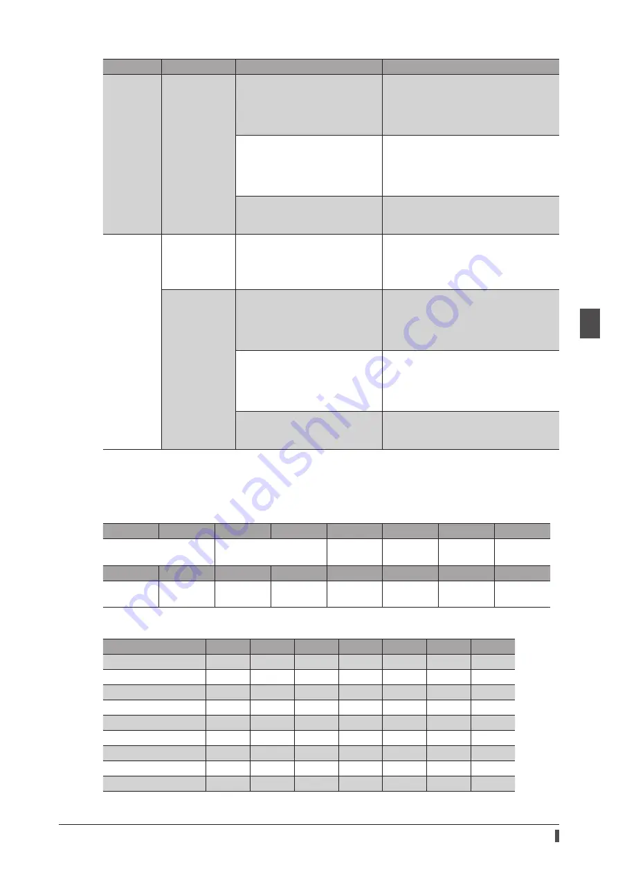
Status output of drive state machine
The status of the drive state machine is output by the Statusword object (6041h).
z
Statusword object (6041h)
Bit 15
Bit 14
Bit 13
Bit 12
Bit 11
Bit 10
Bit 9
Bit 8
Manufacturer specific (ms)
Operation mode specific
(oms)
Internal
limit active
Target
reached
Remote
ms
Bit 7
Bit 6
Bit 5
Bit 4
Bit 3
Bit 2
Bit 1
Bit 0
Warning
Switch on
disabled
Quick stop
Voltage
enabled
Fault
Operation
enabled
Switched
on
Ready to
switch on
z
Status output of Statusword
State
Bit 6
Bit 5
Bit 4
Bit 3
Bit 2
Bit 1
Bit 0
Start
0
0
0
0
0
0
0
Not ready to switch on
0
0
0
0
0
0
0
Fault
0
1
− *
1
0
0
0
Fault reaction active
0
1
− *
1
1
1
1
Switch on disabled
1
1
− *
0
0
0
0
Ready to switch on
0
1
− *
0
0
0
1
Switched on
0
1
− *
0
0
1
1
Operation enabled
0
1
− *
0
1
1
1
Quick stop active
0
0
− *
0
1
1
1
* “Voltage enabled” changes to 1 while the main power is supplied.
Summary of Contents for aSTEP AZ mini Driver
Page 14: ...14 1 Introduction...
Page 128: ...128 3 EtherCAT communication...
Page 146: ...146 4 Object list...
Page 164: ...164 5 Troubleshooting...
Page 170: ...170 6 Reference materials...
Page 171: ...171 6 Reference materials...


