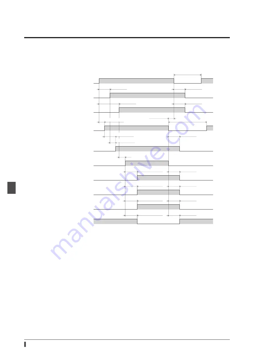
Timing chart
166
6 R
ef
1
Timing chart
Power activation
z
When a control power supply is used
10 s or more
0 s or more
1 s or less
1 s or less
1 s or less
1 s or less
2 s or less
*1
1 s or less
1.25 s or less *2
1 s or less
1.25 s or less *2
1 s or less
1.2 s or less *2
1 s or less
1.25 s or less *2
Control power supply
Main power supply
OFF
ON
MPS output
OFF
ON
OFF
ON
EtherCAT communication
preparation
Not completed
Completed
SYS-RDY (ready to read output,
ready to accept input)
Not ready
Ready
Excitation command reception
Not possible
Possible
READY output
OFF
ON
DCMD-RDY output
OFF
ON
Motor excitation
Non-excitation
Excitation
Electromagnetic brake
Release
Hold
10 s or more
3 s or less
0 s or more
0 s or more
*1 It varies depending on the timing when the command is transitioned from the EtherCAT master.
*2 It represents when the excitation command is received at the same time as the excitation command reception has
changed “Possible.”
Summary of Contents for aSTEP AZ mini Driver
Page 14: ...14 1 Introduction...
Page 128: ...128 3 EtherCAT communication...
Page 146: ...146 4 Object list...
Page 164: ...164 5 Troubleshooting...
Page 170: ...170 6 Reference materials...
Page 171: ...171 6 Reference materials...


