background image

4-1 Installation Conditions 

4-1-2 Servomotors


 Keeping Foreign Objects Out of Units 

  Place a cover over the Units or take other preventative measures to prevent foreign 

objects, such as drill filings, from getting into the Units during installation. Be sure to 
remove the cover after installation is complete. If the cover is left on during operation, 
heat buildup may damage the Units. 

  Take measures during installation and operation to prevent foreign objects such as 

metal particles, oil, machining oil, dust, or water from getting inside of Servo Drivers. 


4-1-2 Servomotors 

 Operating Environment 

The environment in which the Servomotor is operated must meet the following conditions. 
Operating the Servomotor outside of the following ranges may result in malfunction of the 
Servomotor. 

  Ambient operating temperature: 0 to +40°C 

  Ambient operating humidity: 20% to 80% (with no condensation) 

  Atmosphere: No corrosive gases. 

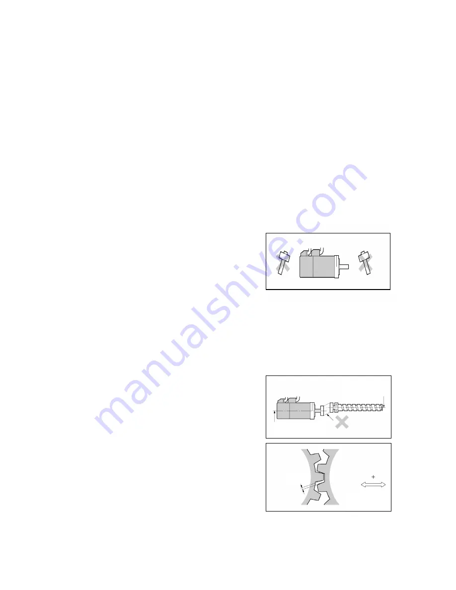
 Impact and Load 

  The Servomotor is resistant to impacts of 

up to 98 m/s

2

. Do not subject it to heavy 

impacts or loads during transport, 
installation, or removal.   


  When transporting it, hold onto the 

Servomotor itself, and do not hold onto the 
encoder, cable, or connector areas. 
Holding onto weaker areas such as these 
can damage the Servomotor.   

  Always use a pulley remover to remove 

pulleys, couplings, or other objects from 
the shaft. 

  Secure cables so that there is no impact o

load placed on the cable connector areas. 


 Connecting to Mechanical Systems 

  The axial loads for Servomotors are 

specified in 

3-2-2 Characteristics

. If an 

axial load greater than that specified is 
applied to a Servomotor, it will reduce the 
service life of the motor bearings and may 
damage the motor shaft. 

Ball screw center line


Do not offset center lines.

Servomotor shaft
center line


Backlash

Adjust backlash by
adjusting the 
distance between 
shafts.


  When connecting to a load, use couplings 

that can sufficiently absorb mechanical 
eccentricity and variation.   

  For spur gears, an extremely large radial 

load may be applied depending on the 
gear precision. Use spur gears with a high 
degree of accuracy (for example, JIS class 
2: normal line pitch error of 6 µm max. for 
a pitch circle diameter of 50 mm).   

  If the gear precision is not adequate, allow 

backlash to ensure that no radial load is 
placed on the motor shaft. 

4-3


Summary of Contents for SMARTSTEP Junior R7D-ZP

Page 1: ...USER S MANUAL SMARTSTEP Junior Servomotors Servo Drivers MODELS R7M Z Servomotors R7D ZP Servo Drivers Cat No I553 E1 01 ...

Page 2: ...erstand its contents before attempting to operate the product Please keep this manual handy for future reference after reading it Be sure that this manual accompanies the product to its final user OMRON 2006 All rights reserved No part of this publication may be reproduced stored in a retrieval system or transmitted in any form or by any means mechanical electronic photocopying recording or otherw...

Page 3: ...2 ...

Page 4: ...DETERMINED THAT THE PRODUCTS WILL SUITABLY MEET THE REQUIREMENTS OF THEIR INTENDED USE OMRON DISCLAIMS ALL OTHER WARRANTIES EXPRESS OR IMPLIED LIMITATIONS OF LIABILITY OMRON SHALL NOT BE RESPONSIBLE FOR SPECIAL INDIRECT OR CONSEQUENTIAL DAMAGES LOSS OF PROFITS OR COMMERCIAL LOSS IN ANY WAY CONNECTED WITH THE PRODUCTS WHETHER SUCH CLAIM IS BASED ON CONTRACT WARRANTY NEGLIGENCE OR STRICT LIABILITY I...

Page 5: ...at the uses listed may be suitable for the products Outdoor use uses involving potential chemical contamination or electrical interference or conditions or uses not described in this manual Nuclear energy control systems combustion systems railroad systems aviation systems medical equipment amusement machines vehicles safety equipment and installations subject to separate industry or government re...

Page 6: ...firm actual specifications of purchased products DIMENSIONS AND WEIGHTS Dimensions and weights are nominal and are not to be used for manufacturing purposes even when tolerances are shown PERFORMANCE DATA Performance data given in this manual is provided as a guide for the user in determining suitability and does not constitute a warranty It may represent the result of OMRON s test conditions and ...

Page 7: ...Please keep this manual close at hand for future reference The following conventions are used to indicate and classify precautions in this manual Always heed the information provided with them Failure to heed precautions can result in injury to people or damage to property Indicates a potentially hazardous situation which if not avoided could result in death or serious injury Additionally there ma...

Page 8: ...d by authorized personnel Not doing so may result in electric shock or injury Wiring or inspection must not be performed for at least five minutes after turning OFF the power supply Doing so may result in electric shock Do not damage press or put excessive stress or heavy objects on the cables Doing so may result in electric shock Do not touch the rotating parts of the Servomotor in operation Doin...

Page 9: ...Locations subject to corrosive or flammable gases Locations subject to dust especially iron dust or salts Locations subject to shock or vibration Locations subject to exposure to water oil or chemicals Do not touch the Servo Driver radiator Servo Driver regeneration resistor or Servomotor while the power is being supplied or soon after the power is turned OFF Doing so may result in a skin burn due...

Page 10: ...malfunction Use crimp terminals for wiring Do not connect bare stranded wires directly to terminals Connection of bare stranded wires may result in burning Always use the power supply voltage specified in the User s Manual An incorrect voltage may result in malfunction or burning Take appropriate measures to ensure that the specified power with the rated voltage and frequency is supplied Be partic...

Page 11: ...ine Not doing so may cause injury When an alarm occurs remove the cause reset the alarm after confirming safety and then resume operation Not doing so may result in injury Do not use the built in brake of the Servomotor for ordinary braking Doing so may result in malfunction Do not operate the Servomotor connected to a load that exceeds the applicable load moment of inertia Doing so may result in ...

Page 12: ...rnings Warning Labels Warning labels are pasted on the product as shown in the following illustration Be sure to follow the instructions given there Warning label Example from R7D ZP01H Warning Label Contents 11 ...

Page 13: ...Servo Driver is damaged or some other fault exists please contact the point of purchase or your OMRON representative Interpreting the Model Number The model number provides information such as the Servo Driver type the applicable Servomotor capacity and the power supply voltage R7D ZP01H SMARTSTEP Junior Servo Driver Driver Type P Pulse string input Applicable Servomotor Capacity 01 100 W 02 200 W...

Page 14: ...13 Section 1 Features and System Configuration Section 2 Standard Models and Dimensions Section 3 Specifications Section 4 System Design Section 5 Operation Section 6 Troubleshooting Appendix ...

Page 15: ...e train Input Servo Driver 1 6 1 5 Applicable Standards 1 7 1 5 1 EC Directives 1 7 1 5 2 UL and cUL Standards 1 7 Section 2 Standard Models and Dimensions 2 1 Standard Models 2 2 2 1 1 Servo Drivers 2 2 2 1 2 Servomotors 2 2 2 1 3 Servo Driver Servomotor Combinations 2 2 2 1 4 Decelerators Straight Shaft with Key 2 3 2 1 5 Accessories and Cables 2 4 2 2 External and Mounted Dimensions 2 5 2 2 1 S...

Page 16: ...ation Resistance Unit 3 24 3 5 1 Regeneration Resistance Unit R88A RG08UA Specifications 3 24 3 6 AC Reactors 3 26 3 6 1 AC Reactor Specifications 3 26 Section 4 System Design 4 1 Installation Conditions 4 2 4 1 1 Servo Drivers 4 2 4 1 2 Servomotors 4 3 4 1 3 Decelerators 4 5 4 2 Wiring 4 6 4 2 1 Connecting Cables 4 6 4 2 2 Selecting Connecting Cables 4 7 4 2 3 Peripheral Device Connection Example...

Page 17: ...2 Precautions When Troubleshooting 6 3 6 1 3 Replacing the Servomotor and Servo Driver 6 3 6 2 Alarm Table 6 4 6 2 1 Alarm Table 6 4 6 3 Troubleshooting 6 5 6 3 1 Error Diagnosis using the Alarm Indicators 6 5 6 3 2 Error Diagnosis using the Operating Status 6 8 6 4 Overload Characteristics Electronic Thermal Function 6 11 6 4 1 Overload Characteristics Graphs 6 11 6 5 Periodic Maintenance 6 12 6 ...

Page 18: ...Section 1 Configuration Features and System ...

Page 19: ... control 1 1 2 SMARTSTEP Junior Features The SMARTSTEP Junior has the following features No Setup Parameters No parameter settings are required for setup so you can start using the Servo Driver immediately simply by removing it from the box and wiring it If it is necessary to set the positioning resolution or reference pulse method these settings can be set or changed easily with the rotary switch...

Page 20: ...ntrol Unit with pulse string output SYSMAC PLC with pulse output functions Flexible Motion Controller with pulse I O SYSMAC CJ1 CS1 C series Programmable Controller SMARTSTEP Junior Servo Driver R7D ZP SMARTSTEP Junior Servomotor R7M Z Pulse string Position Control Unit 1 3 ...

Page 21: ...rvomotor power Power supply indicator PWR Rotary switch for setting command filter FIL Control I O connector CN1 Rotary Switch for Setting Command Pulse PULSE Always turn OFF the power supply before setting the rotary switch The switch is factory set to 0 Setting Command pulse resolution Command pulse connection method Command pulse type 0 1000 1 2500 Open collector or line driver 2 5000 3 10000 L...

Page 22: ...ng or stopping 2 The settling time depends on the commanded acceleration deceleration the rigidity of the machine motor drive the encoder resolution and other factors 3 Use the acceleration deceleration times as a guideline for determining the Servomotor capacity that can be driven when using STEP commands without commanded acceleration deceleration Command Indicators REF Indicator See note Power ...

Page 23: ...ve MPU ASIC Position speed and torque processor ADC FAN G VCC Fan alarm VCC G A A B B Phase U Phase V Phase W Phase Z Set value read circuit Command format setting Command filter setting I O and drive circuits Display circuit CW input Alarm output INP output Brake output Origin output Run input CCW input L1 L2 N P U V W GR GR Control I O connector Encoder signal input connector Control power suppl...

Page 24: ...ic and medical radio frequency equipment EMC Directive AC Servo Drivers and AC Servomotors EN 61000 6 2 Electromagnetic compatibility EMC Immunity standard for industrial environments Note To conform to EMC Directives the Units must be installed under the conditions described in 4 2 5 Conforming to EMC Directives 1 5 2 UL and cUL Standards Standard Product Applicable standards File number Comments...

Page 25: ...1 5 Applicable Standards 1 5 2 UL and cUL Standards 1 8 ...

Page 26: ...Section 2 Dimensions Standard Models and ...

Page 27: ... S1 100 W R7M Z10030 BS1 200 W R7M Z20030 BS1 400 W R7M Z40030 BS1 With brake 750 W R7M Z75030 BS1 2 1 3 Servo Driver Servomotor Combinations Servomotor Servo Driver Rated output Without brake With brake Pulse string input 100 W R7M Z10030 S1 R7M Z10030 BS1 R7D ZP01H 200 W R7M Z20030 S1 R7M Z20030 BS1 R7D ZP02H 400 W R7M Z40030 S1 R7M Z40030 BS1 R7D ZP04H 750 W R7M Z75030 S1 R7M Z75030 BS1 R7D ZP0...

Page 28: ...9C400 1 15 R7G VRSFPB15C400 200 W 1 25 R7G VRSFPB25C200 1 5 R7G VRSFPB05C400 1 9 R7G VRSFPB09C400 1 15 R7G VRSFPB15C400 400 W 1 25 R7G VRSFPB25D400 1 5 R7G VRSFPB05C750 1 9 R7G VRSFPB09D750 1 15 R7G VRSFPB15D750 750 W 1 25 R7G VRSFPB25E750 Backlash 45 Arcminutes Max Specifications Motor capacity Gear ratio Model 1 5 R7G RGSF05B100 1 9 R7G RGSF09B100 100 W 1 15 R7G RGSF15B100 1 5 R7G RGSF05B200 1 9...

Page 29: ...odel 3 m R7A CRZ003C 5 m R7A CRZ005C Encoder Cables connector attached 10 m R7A CRZ010C Cable Only in 1 m increments R7A CRZ001 Connectors Specifications Model Main Circuit Connector CNA with Ejector Levers R7A CNZ01P Servomotor Connector CNB R7A CNZ01A Control Input Connector CN1 R7A CNA01R Encoder Input Connector CN2 R7A CNZ01R Servomotor Connector for Encoder Cable R7A CNZ02R Servomotor Connect...

Page 30: ...2 2 External and Mounted Dimensions 2 2 1 Servo Drivers R7D ZP01H ZP02H 100 W 200 W Footprint 4 5 dia hole Two M4 screw holes Mounting pitch Mounting Hole Dimensions R7D ZP04H 400 W 4 5 dia hole Two M4 screw holes Mounting pitch Mounting Hole Dimensions 2 5 ...

Page 31: ...2 2 External and Mounted Dimensions 2 2 1 Servo Drivers R7D ZP08H 750 W Exterior 4 5 dia hole Two M4 screw holes Mounting pitch Mounting Hole Dimensions 2 6 ...

Page 32: ...motors 2 2 2 Servomotors 100 W Servomotor without a Brake R7M Z10030 S1 Key groove Key 8 dia height 6 46 dia Two 4 3 dia 30 dia height 8 100 W Servomotor with Brake R7M Z10030 BS1 Key groove Key 8 dia height 6 30 dia height 8 46 dia Two 4 3 dia 2 7 ...

Page 33: ... 148 5 118 5 93 30 60 70 50h8 6 Four 5 5 dia 14h6 20 400 R7M Z75030 S1 173 133 107 5 40 80 90 70h8 8 Four 7 dia 16h6 30 750 200 W 400 W 750 W Servomotors with Brakes R7M Z20030 BS1 Z40030 BS1 Z75030 BS1 Output Section on 750 W Servomotor Key Key groove S dia D2 dia D1 dia Model L mm LL mm LM mm LR mm C mm D1 mm D2 mm G mm Z mm S mm QK mm Output w R7M Z20030 BS1 165 5 135 5 70 30 60 70 50h8 6 Four ...

Page 34: ... 62 17 3 8 19 30 M5 M6 M4 20 22 6 6 3 5 2 1 200 W 1 25 R7G VRSFPB25C200 100 50 78 60 70 90 70 62 17 3 8 19 30 M5 M6 M4 20 22 6 6 3 5 2 1 1 5 R7G VRSFPB05C400 89 5 50 78 60 70 90 70 62 17 3 8 19 30 M5 M6 M4 20 22 6 6 3 5 1 7 1 9 R7G VRSFPB09C400 89 5 50 78 60 70 90 70 62 17 3 8 19 30 M5 M6 M4 20 22 6 6 3 5 1 7 1 15 R7G VRSFPB15C400 100 50 78 60 70 90 70 62 17 3 8 19 30 M5 M6 M4 20 22 6 6 3 5 2 1 40...

Page 35: ...05B200 72 5 32 52 60 70 60 50 45 10 3 10 12 20 M5 M5 M4 12 16 4 4 2 5 0 72 1 9 R7G RGSF09C400 89 5 50 78 60 70 90 70 62 17 3 8 19 30 M5 M6 M4 20 22 6 6 3 5 1 7 200 W 1 15 R7G RGSF15C400 100 50 78 60 70 90 70 62 17 3 8 19 30 M5 M6 M4 20 22 6 6 3 5 2 1 1 5 R7G RGSF05C400 89 5 50 78 60 70 90 70 62 17 3 8 19 30 M5 M6 M4 20 22 6 6 3 5 1 7 1 9 R7G RGSF09C400 89 5 50 78 60 70 90 70 62 17 3 8 19 30 M5 M6 ...

Page 36: ...Section 3 Specifications ...

Page 37: ...n resistance Between power supply power line terminals and frame ground 0 5 MΩ min at 500 V DC Dielectric strength Between power supply power line terminals and frame ground 1 500 V AC for 1 min at 50 60 Hz Between each control signal and frame ground 500 V AC for 1 min Degree of protection Built into panel IP10 EMC Directive EN 55011 Class A Group 1 EN 61000 6 2 EC Directives Low Voltage Directiv...

Page 38: ...ponse frequency command pulses 750 kpps Weight 0 5 kg 1 0 kg Applicable motor capacity 100 W 200 W 400 W 750 W Applicable Servomotors R7M Z10030 S1 Z20030 S1 Z40030 S1 Z75030 S1 3 1 3 Main Circuit and Servomotor Connector Specifications CNA and CNB R7A CNZ01P CNA Main Circuit Connector Specifications CNA Connector Main Circuit Connector CNA Pin Arrangement Signal No Signal Function Condition 1 L1 ...

Page 39: ...cations CNB Connector Servomotor Connector CNB Pin Arrangement Pin No Terminal label Name Function 1 U Red 2 V White 3 W Servomotor connection Terminals Blue These are the output terminals to the Servomotor Be careful to wire them correctly 4 Do not connect anything to this terminal Frame ground Green Yellow Connect the Servomotor FG terminal 3 4 ...

Page 40: ...fications CN1 Control I O Signal Connections and External Signal Processing Shell Frame ground Reverse pulse Forward pulse Deviation counter reset RUN command Alarm output Brake interlock Positioning completed output Maximum operating voltage 30 V DC Maximum Output Current 50 mA DC Phase Z 3 5 ...

Page 41: ...11 ZCOM Phase Z output Outputs the Encoder s phase Z 1 pulse revolution Note Use the rising edge of the ON signal 12 ALM Alarm output When the Servo Driver generates an alarm the output turns OFF Note OFF for approx 2 s after the power is turned ON 13 BKIR Brake interlock output Outputs the holding brake timing signals Release the holding brake when this signal is ON 14 INP Positioning completed o...

Page 42: ...put Circuits Position Command Pulse Inputs and Deviation Counter Reset Inputs Line Driver Input Controller Servo Driver Applicable line driver SN75174 MC3487 AM26LS31A equivalent Input current 9 mA 3 V Open Collector Input Controller Servo Driver Input current 7 to 15 mA Note Select a value for resistance R so that the input current will be from 7 to 15 mA Vcc R 24 V 1 6 to 2 2 kΩ 12 V 750 to 1 kΩ...

Page 43: ...d Pulse CCW Signal Functions The functions of these signals depend on the setting of the command pulse rotary switch PULSE on the front of the Servo Driver Turn OFF the Servo Driver s power before setting the PULSE Switch The factory setting is 0 Setting Command pulse resolution Command pulse connection method Command pulse type 0 1000 1 2500 Open collector or line driver 2 5000 3 10000 Line drive...

Page 44: ...mand Forward pulse Reverse pulse Deviation Counter Reset ECRST The CN1 connector input pins are as follows Deviation Counter Reset 8 ECRST Deviation Counter Reset 9 ECRST Functions The value of the deviation counter will be reset when the deviation counter reset signal turns ON and the position loop will be disabled Input the reset signal for 20 µs minimum The counter will not be reset if the sign...

Page 45: ...and Alarm Outputs Servo Driver Maximum operating voltage 30 V DC Maximum output current 50 mA External power supply 24 V DC 1 V Di Diode for preventing surge voltage Use speed diodes 3 1 8 Control Output Details Control Output Sequence Power supply input L1 and L2 Positioning Completed Output INP Brake Interlock output BKIR Run command input RUN Approx 2 s 0 to 35 ms 2 ms 30 s max Alarm output ALM...

Page 46: ...ompleted Output INP Function The INP signal turns ON when the number of accumulated pulses in the deviation counter is less than 10 3 1 9 Encoder Connector Specifications CN2 Pin No Signal Name Function interface 1 E5V Encoder power supply 5 V 2 E0V Encoder power supply GND Power supply output for the encoder 5 V 70 mA 3 Phase A Encoder phase A input 4 Phase A Encoder phase A input Differential si...

Page 47: ...s 3 1 9 Encoder Connector Specifications CN2 Crimped Solderless Connector Name Model Maker Plug Cable and Cover Set 54559 1005 Plug Housing 51209 1001 Crimp Terminal 59351 8187 Loose wire Crimping Tool 57401 5300 Molex Japan Co 3 12 ...

Page 48: ...istance 98 m s2 max twice in vertical direction Insulation resistance 10 MΩ min at 500 VDC between the power terminals and FG terminal Dielectric strength 1 500 VAC 50 or 60 Hz for 1 minute between the power terminals and FG terminal Operating position Any direction Insulation class Type B Construction Totally enclosed self cooling Degree of protection IP55 excluding the through shaft portion Vibr...

Page 49: ...note 3 V 24 VDC 10 Power consumption at 20 C W 6 7 7 7 7 Current consumption at 20 C A 0 25 0 29 0 29 0 32 Static friction torque N m 0 318 min 0 637 min 1 27 min 2 45 min Attraction time See note 4 ms 60 max 80 max Release time See note 4 ms 30 max 20 max Backlash 1 max Brake specifications Rating Continuous Applicable Servo Drivers R7D Pulse train models ZP01H ZP02H ZP04H ZP08H Note 1 These are ...

Page 50: ...cs The following graphs show the characteristics with a 3 m standard cable and a 200 V AC input R7M Z10030 S1 Repetitive usage Continuous usage R7M Z20030 S1 R7M Z40030 S1 R7M Z75030 S1 Repetitive usage Continuous usage Repetitive usage Continuous usage Repetitive usage Continuous usage 3 15 ...

Page 51: ...tures In particular in systems that use a Decelerator the load torque at low temperatures may be nearly twice the load torque at normal temperatures Check with a current monitor to see whether there is overloading at low temperatures Also check operation at high temperatures to see whether there is abnormal Servomotor overheating or alarms An increase in load friction torque visibly increases load...

Page 52: ...W 1 25 R7G VRSFPB25D400 120 26 4 83 180 79 3 2 79 10 5 1617 808 1 5 R7G VRSFPB05C750 600 10 8 90 900 32 0 7 17 10 5 784 392 1 9 R7G VRSFPB09D750 333 18 3 85 500 54 3 6 50 10 5 1176 588 1 15 R7G VRSFPB15D750 200 30 5 85 300 90 5 7 09 10 5 1372 686 750 W 1 25 R7G VRSFPB25E750 120 50 8 85 180 151 7 05 10 5 2058 1029 Note 1 The Decelerator inertia is the Servomotor shaft conversion value 2 The enclosu...

Page 53: ...gth L Outer diameter of cable Weight R7A CPZ001S 1 m Approx 0 1 kg R7A CPZ002S 2 m 5 6 dia Approx 0 2 kg Connection Configuration and Dimensions Controller end Servo Driver end R7D ZP Wiring No Wire color Mark color Signal 1 Orange Red CW PULS 2 Orange Black CW PULS 3 Gray Red CCW SIGN 4 Gray Black CCW SIGN 5 White Red 24VIN 6 Yellow Black RUN 7 White Black OGND 8 Pink Red ECRST 9 Pink Black ECRST...

Page 54: ...B Connector for Servomotors without Brakes Cable Models Model Length L Outer diameter of cable Weight R7A CAZ003S 3 m Approx 0 4 kg R7A CAZ005S 5 m Approx 0 8 kg R7A CAZ010S 10 m 7 4 dia Approx 1 2 kg Note The maximum distance between the Servo Driver and Servomotor is 20 meters Connection Configuration and Dimensions Servo Driver end Servomotor end R7M Z R7D ZP Wiring Servo Driver No 1 2 3 4 5 6 ...

Page 55: ...l Length L Outer diameter of cable Weight R7A CAZ003B 3 m Approx 0 4 kg R7A CAZ005B 5 m Approx 0 8 kg R7A CAZ010B 10 m 7 4 dia Approx 1 2 kg Note The maximum distance between the Servo Driver and Servomotor is 20 meters Connection Configuration and Dimensions Servo Driver end Servomotor end R7M Z R7D ZP Wiring Servo Driver No 1 2 3 4 5 6 Signal Servomotor No 1 2 3 4 Signal Phase U Phase V Phase W ...

Page 56: ... The Encoder Cable connects the encoder between the Servo Driver and Servomotor Encoder Cables are available in two forms Encoder Cables with an attached CN2 Connector and plain cable only Note When connecting to moving parts use robot cable to make a custom cable Encoder Cable CN2 Connector Attached Cable Models Model Length L Outer diameter of cable Weight R7A CRZ003C 3 m Approx 0 4 kg R7A CRZ00...

Page 57: ... AWG26 Yellow White AWG26 Yellow AWG26 Blue White Connector plug 5557 12R 210 Connector case 5556T2L JST Mfg Co Ltd Encoder Cable Loose Wires Only Cable Models Model Length L Outer diameter of cable Weight R7A CRZ001 1 m 7 1 dia Approx 0 1 kg Note 1 The maximum distance between the Servo Driver and Servomotor is 20 meters 2 Cable are sold in 1 m increments It is cut to the specified length 3 4 4 C...

Page 58: ...Specifications 3 4 4 Connector Specifications Servomotor Connector R7A CNZ01A The Servomotor Connector connects to the Servo Driver s Servomotor Connector CNB Dimensions Servomotor Connector 04JFAT SAYGF N JST Mfg Co Ltd 3 23 ...

Page 59: ...re and overvoltage Alarm output Single pole NC contact open when protection function is operating can handle 200 VAC Dimensions 55 160 130 mm W H D LED Indicator Specifications Item Specifications POWER Lit when power is being supplied to the P and N terminals REGEN Lit during regeneration operation ALARM REGEN Lit when the regeneration resistance is disconnected or the regeneration transistor fai...

Page 60: ...3 5 Regeneration Resistance Unit 3 5 1 Regeneration Resistance Unit R88A RG08UA Specifications Dimensions Mounting Hole Dimensions Two M4 6 dia 3 25 ...

Page 61: ...o Driver model Model Rated current A Inductance mH Weight kg R7D ZP01H R88A PX5052 1 0 45 0 Approx 0 4 R7D ZP02H R88A PX5053 2 0 20 0 Approx 0 6 R7D ZP04H R88A PX5054 3 0 5 0 Approx 0 4 R7D ZP08H R88A PX5056 5 0 2 0 Approx 0 4 Dimensions Nameplate Units mm Four H dia Model A B C D E F G H dia I dia R88A PX5052 35 52 80 95 30 40 45 4 4 3 R88A PX5053 35 52 90 105 35 45 50 4 4 3 R88A PX5054 35 52 80 ...

Page 62: ...Section 4 System Design ...

Page 63: ... corrosive gases Ambient Temperature Servo Drivers should be operated in environments in which there is minimal temperature rise to maintain a high level of reliability Temperature rise in any Unit installed in a closed space such as a control box will cause the Servo Driver s ambient temperature to rise Use a fan or air conditioner to prevent the Servo Driver s ambient temperature from exceeding ...

Page 64: ...nstallation or removal When transporting it hold onto the Servomotor itself and do not hold onto the encoder cable or connector areas Holding onto weaker areas such as these can damage the Servomotor Always use a pulley remover to remove pulleys couplings or other objects from the shaft Secure cables so that there is no impact o load placed on the cable connector areas r Connecting to Mechanical S...

Page 65: ...If an excessive radial load is applied the motor shaft and bearings may be damaged Set up a movable pulley between the motor axis and the load axis so that the belt tension can be adjusted Pulley for tension adjustment Make adjustable Pulley Belt Tension Water and Drip Resistance The enclosure ratings for the Servomotors are as follows IP55 except for through shaft parts and cable exit holes Other...

Page 66: ...ubber cap and check that the set bolt is loose 2 Insert the Servomotor shaft into the input shaft 3 Tighten the Servomotor installation bolt to the torque specified in the following table Servomotor installation bolt Tightening torque N m M4 2 9 M5 5 8 M6 9 8 4 Tighten the set bolt to the torque specified in the following table Set bolt Tightening torque N m M3 1 0 M4 2 9 5 After tightening the se...

Page 67: ...3 Flexible Motion Controller FQM1 MMP21 22 Position Control Unit with a pulse string output CJ1W NC113 133 CJ1W NC213 233 CJ1W NC413 433 CS1W NC113 133 CS1W NC213 233 CS1W NC413 433 C200HW NC113 C200HW NC213 C200HW NC413 Position Control Unit General purpose Control Cable and Control I O Connector Servo Relay Unit Cable Connector Terminal Block and Cable CN1 Control I O Connector CN2 Encoder Input...

Page 68: ... either 1 m or 2 m Example model number R7A CPZ001S 1 m Servomotor Power Cables CNB There are two kinds of Servomotor Power Cables one for Servomotors with a brake and another for Servomotors without a brake Select the Cable to match the Servomotor being used Specification Model number Comments For a Servomotor without a brake R7A CAZ S For a Servomotor with a brake R7A CAZ B The digits in the mod...

Page 69: ...vice Control cable See note 2 Note 1 Recommended products are listed in 4 2 5 Conforming to EMC Directives 2 Recommended Relay OMRON MY series Relay 24 V model 3 An R88A RR22047S External Regeneration Resistor can be connected Connect the R88A RR22047S if the regenerative energy exceeds the capacity of the External Regeneration Unit Connect the R88A RR22047S so that the power supply is cut off whe...

Page 70: ...al Ground to a minimum of 100 Ω class D class 3 Terminal Block Wire Sizes Model R7D Item Unit ZP01H ZP02H ZP04H ZP08H Power supply capacity kVA 0 4 0 75 1 2 2 2 Rated current A rms 1 8 3 5 5 5 10 Main circuit power supply input L1 L2 Wire size mm2 1 25 2 0 External Regeneration Unit connection terminals Wire size mm2 1 25 Wiring length 0 5 m max Rated current A rms 0 84 1 1 2 0 3 7 Maximum momenta...

Page 71: ...nnector 1 Remove the Terminal Block from the Servo Driver The Terminal Block must be removed from the Servo Driver before being wired The Servo Driver will be damaged if the wiring is done with the Terminal Block in place 2 Strip the covering off the ends of the wires Prepare wires of the right sizes according to the tables provided under Terminal Block Wire Sizes above and strip off 9 to 10 mm of...

Page 72: ...e configuration wiring and other conditions of the equipment in which the products are installed The customer must therefore perform final checks to confirm that devices and the overall installation conform to EMC Directives The following conditions must be met to conform to EMC Directives The Servo Driver must be installed in a metal case control panel The Servomotor does not however have to be c...

Page 73: ...a single point Use ground lines with a minimum thickness of 3 5 mm 2 and arrange the wiring so that the ground lines are as short as possible No fuse breakers surge absorbers and noise filters NF should be positioned near the input terminal block ground plate and I O lines should be isolated and wired using the shortest distance possible If no fuse breakers are installed at the top and the power s...

Page 74: ...oint areas or mask them during painting to make them electrically conductive If gaps appear in the control box case when screws are tightened make adjustments to prevent this from occurring Do not leave any conductive part unconnected Ground all Units within the case to the case itself Door Structure Use a door that is made of metal Use a water draining structure where the door and case fit togeth...

Page 75: ...tions when selecting the components For more details contact the manufacturers directly Fuses Always install a fuse at each Servo Driver to prevent fire or burn damage We recommend the following fuses based on the rated current current at the maximum momentary torque and inrush current when the power is turned ON Servo Driver Fuse Littelfuse Inc Fuse block Littelfuse Inc Model Capacity W Momentary...

Page 76: ... rated current flows for 0 02 second When there is a simultaneous inrush for multiple Servo Drivers select a no fuse breaker with a 20 ms allowable current greater than the total inrush current for those Servo Drivers shown in the following table Inrush current A0 p Servo Driver model Main circuit power supply R7D ZP01H ZP02H ZP04H 30 R7D ZP08H 60 Surge Absorbers Use surge absorbers to absorb surg...

Page 77: ... wires the 06 models have fast on connections that can be soldered and the 08 models have screw terminals Select the appropriate version for your application Contact the manufacturer www schaffner com for details Dimensions The following diagram shows the dimensions of a noise filter with lead wires Contact the manufacturer for dimensions of the noise filters with other connections Dimensions mm S...

Page 78: ...ge Select the varistor voltage as follows 24 VDC system 39 V 100 VDC system 200 V 100 VAC system 270 V 200 VAC system 470 V Capacitor resistor The capacitor resistor combination is used to absorb vibration in the surge when power is cut off The reset time can be shortened by selecting the appropriate capacitance and resistance Okaya Electric Industries Co Ltd XEB12002 0 2 µF 120 Ω XEB12003 0 3 µF ...

Page 79: ...P01H ZP02H ZP04H 3 mA max R7D ZP08H 5 mA max Note 1 The leakage current shown above is for Servomotor power cables less than 5 meters long The leakage current depends on the power cable length and the insulation 2 The leakage current shown above is for normal temperature and humidity The leakage current depends on the temperature and humidity The following table shows the recommended leakage break...

Page 80: ... errors can occur if control I O is influenced by noise Follow the methods outlined below for the power supply and wiring Use completely separate power supplies for the control power supply especially 24 V DC and the external operation power supply In particular do not connect the two power supply ground wires Install a noise filter on the primary side of the control power supply If Servomotors wi...

Page 81: ...noise at low frequencies below 200 kHz use an isolation transformer and a noise filter 2 To attenuate noise at high frequencies over 30 MHz use a ferrite core and a high frequency noise filter with a through type capacitor 3 If multiple Servo Drivers are being connected to a single noise filter select a noise filter with a rated current at least two times the total rated current of all the Servo D...

Page 82: ...egenerative Energy Horizontal Axis Servomotor operation Servomotor output torque Note In the output torque graph acceleration in the positive direction is shown as positive and acceleration in the negative direction is shown as negative The regenerative energy values for each region can be derived from the following equations 1 1 1 1 60 2 2 1 t T N E D g π J J 1 1 1 0524 0 t T N D 2 2 2 2 60 2 2 1...

Page 83: ...aph acceleration in the positive direction rising is shown as positive and acceleration in the negative direction falling is shown as negative The regenerative energy values in each region can be derived from the following equations 1 1 1 1 60 2 2 1 t T N E D g π J J 1 1 1 0524 0 t T N D 2 2 2 2 60 2 t T N E L g π J J 2 2 2 105 0 t T N L 3 2 2 3 60 2 2 1 t T N E D g π J J 3 2 2 0524 0 t T N D N1 N...

Page 84: ...nal to the square of the rotation speed Lengthen the deceleration time to decrease the regenerative energy produced per time unit Lengthen the operation cycle i e the cycle time to decrease the average regenerative power Servo Driver Regenerative energy J that can be absorbed by the internal capacitor R7D ZP01H 13 R7D ZP02H 19 R7D ZP04H 28 R7D ZP08H 59 4 3 3 Absorbing Regenerative Energy with an E...

Page 85: ...h output 1 5 dia 0 3 mm 2 3 dia 0 75 mm 2 Wiring the External Regeneration Resistor When installing an External Regeneration Resistor remove the shorting bar between the RG JP terminals and connect the resistor to the P RG terminals External Regeneration Resistor Note Connect the thermal switch output just like the External Regeneration Resistance Unit s ALM output so that the power supply will be...

Page 86: ...Section 5 Operation ...

Page 87: ...n 4 2 Switch settings Make sure that the power supply is turned OFF and set the Servo Driver s front panel switches Section 5 2 Preparing for operation After checking the necessary items turn ON the Unit s power supply Check to see whether there are any internal errors in the Servo Driver Section 5 3 Trial operation Firstly check the Servomotor s no load operation Next turn the power OFF then ON a...

Page 88: ...switch is factory set to 0 Setting Command pulse resolution Command pulse connection method Command pulse type 0 1000 1 2500 Open collector or line driver 2 5000 3 10000 Line driver CW CCW positive logic CW CCW 4 1000 5 2500 Open collector or line driver 6 5000 7 10000 Line driver CW CCW negative logic CW CCW 8 1000 9 2500 Open collector or line driver A 5000 B 10000 Line driver pulse string posit...

Page 89: ...70 to 340 ms 5 80 ms 200 to 400 ms 6 85 ms 250 to 500 ms 7 170 ms 500 to 1000 ms Smaller filter time constant short positioning time Larger filter time constant longer positioning time with little vibration 8 to F Do not set this switch to 8 to F Note 1 Increase the value of the filter setting if there is vibration when starting or stopping 2 The settling time depends on the commanded acceleration...

Page 90: ... the Servomotor Do not connect to the mechanical system The Servomotor s power lines and Servomotor Power Cable must be connected securely The Encoder Cable must be securely connected to the Encoder Connector CN2 at the Servo Driver The Encoder Cable must be securely connected to the Encoder Connector at the Servomotor Checking the Control Connectors The Control Cable must be securely connected to...

Page 91: ...5 3 Preparing for Operation 5 3 1 Turning ON the Power and Checking Indicators 5 6 Check that the command indicator is lit orange or green ...

Page 92: ...that the power and the RUN command can be turned OFF so that the Servomotor can be immediately turned OFF if an abnormality occurs in the system 5 4 2 Trial Operation 1 No load Operation Turn ON the power supply to the control circuits main circuits and peripheral devices Turn ON the RUN command Check that Servomotor is ON Send a command from the Host Controller to rotate the Servomotor and confir...

Page 93: ...load torque roughly equivalent to the measured value Are the positioning points correct When an operation is repeated is there any discrepancy in positioning Are there any abnormal sounds or vibration Is either the Servomotor or the Servo Driver abnormally overheating Is any error or alarm generated Note 1 If anything abnormal occurs refer to Section 6 Troubleshooting and apply the appropriate cou...

Page 94: ...zed About 40 ms See note 4 Relay operation time See note 1 100 ms max See note 5 See note 3 See note 1 Note 1 The timechart above shows the time it takes from inputting the Run command RUN until the brake being released Take this delay into account when sending the pulse command so that the pulse command is sent after the brake has been released In addition there is some delay between a change in ...

Page 95: ...d Energized Not energized See note 2 See note 1 ALM alarm output Note 1 The Servomotor will continue to rotate due to its momentum for about 15 ms after the Servomotor de energizes until the dynamic brake operates 2 The BKIR brake interlock signal will be turned OFF if the Servomotor rotation speed falls below 100 r min or 500 ms has elapsed since the Servo went OFF ...

Page 96: ...Section 6 Troubleshooting ...

Page 97: ... power supply is correct Check the voltage of the sequence input power supply and verify that the 24 VIN Terminal pin CN1 5 is within the allowed range of 23 to 25 VDC If the voltage is outside of this range there is a risk of malfunction so be sure that the power supply is correct Checking Whether an Alarm Has Occurred Check the alarm indicators AL1 to AL3 on the front of the Servo Driver to see ...

Page 98: ...irst check that there are no personnel in the vicinity of the mechanical equipment and that the equipment will not be damaged even if the Servomotor overruns Before performing the tests verify that you can immediately stop the machine using an emergency stop even if the Servomotor overruns 6 1 3 Replacing the Servomotor and Servo Driver Use the following procedure to replace the Servomotor or Serv...

Page 99: ...ation AL1 AL2 AL3 OFF Encoder error This error occurs when data cannot be read from the Encoder or the expected differential phase signal is not present Check the cables AL1 AL2 AL3 OFF operation Voltage error This error occurs if the voltage between P N is outside of the acceptable range of 170 to 410 V during Check whether the input voltage is between 170 and 253 V AL1 AL2 AL3 OFF Overcurrent Th...

Page 100: ...put the command value correctly AL1 AL2 AL3 Speed error Occurs when the Servomotor starts running or after initiating high speed rotation The Servo Driver is faulty Replace the Servo Driver Occurs when the power is turned ON The Servo Driver is faulty Replace the Servo Driver The U phase V phase W phase or GR wires are wired incorrectly The encoder wires are wired incorrectly Rewire correctly Occu...

Page 101: ...air wires that are at least 0 12 mm2 26 AWG Noise is infiltrating the encoder cable because the cable is too long Shorten the encoder cable to less than 20 m The encoder cable is broken Replace the encoder cable Origin error AL1 AL2 AL3 Encoder error Occurs when the power is turned ON or during operation Faulty encoder Replace the Servomotor The power supply voltage exceeded the allowed range Keep...

Page 102: ... conditions There is a problem with the Servo Driver s installation environment such as the installation direction spacing between Units or surroundings Review the installation conditions so that the Servo Driver s ambient temperature is below 55 C The Servo Driver s cooling is insufficient Improve air circulation and heat dissipation The Servomotor and Servo Driver combination is incorrect Use co...

Page 103: ...y Check the command pulse type Set the Servo Driver s pulse type to match the Controller s command pulse type The Control I O Connector CN1 is wired incorrectly Check the command pulse s voltage Connect a resistor that matches the voltage Check whether the power supply is ON and check the PWR Indicator Turn ON the power supply The power supply is not ON Check the voltage across the power supply te...

Page 104: ...e type and the Servo Driver s command pulse type Set the Servo Driver s pulse type to match the Controller s command pulse type The ambient temperature is too high Verify that the ambient temperature around the Servomotor is below 40 C Lower the ambient temperature to 40 C or less Use a cooler or fan Ventilation is obstructed Check to see whether anything is blocking ventilation Improve ventilatio...

Page 105: ... that meets specifications Noise is infiltrating the encoder cable because the cable is too long Check the length of the encoder cable Shorten the encoder cable to less than 20 m Noise is infiltrating the signal wires because the encoder cable is damaged or the sheath is cut Check the encoder cable for cuts or other damage Correct the encoder cable s pathway to prevent damage Too much noise is rea...

Page 106: ...250 6 mm mounted and an ambient temperature of 40 C so use the Servomotor under these conditions 6 4 1 Overload Characteristics Graphs The following graphs show the characteristics of the load rate and electronic thermal function s operation time R7D ZP01H Servo Driver 100 W Time s Motor torque Note 1 The motor torque indicates the percentage of the rated torque that is applied 2 For example if th...

Page 107: ...d operation Do not attempt to disassemble repair or modify any Units Any attempt to do so may result in malfunction fire or electric shock 6 5 1 Servomotor Maintenance The recommended periodic maintenance schedule is listed below Bearings 20 000 hours Decelerator 20 000 hours These values presume an ambient Servomotor operating temperature of 40 C shaft loads within the allowable range rated opera...

Page 108: ...ecommend that ambient operating temperature and the power ON time be reduced as much as possible to lengthen the maintenance intervals for Servo Drivers The life of aluminum electrolytic capacitors is greatly affected by the ambient operating temperature Generally speaking an increase of 10 C in the ambient operating temperature will reduce capacitor life by 50 The aluminum electrolytic capacitors...

Page 109: ...6 5 Periodic Maintenance 6 5 3 Replacing the Cooling Fan 6 14 ...

Page 110: ...Appendix ...

Page 111: ...r Cable Connect an external Regeneration Resistance Unit when required Red White Blue Green Yellow Linear reactor Fuse Shell Example 2 Connecting to SYSMAC CJ1W NC113 213 413 Position Control Units CJ1W NC113 213 413 R7D ZP R7A CPZ S R7M Z Signal Main circuit power supply Main circuit contact Surge suppressor Servo error indicator 3 phase 200 230 VAC 50 60Hz Ground to 100 Ω or less Noise filter 24...

Page 112: ...motor Power Cable Connect an external Regeneration Resistance Unit when required Red White Blue Green Yellow Linear reactor Fuse Shell Example 4 Connecting to a SYSMAC CP1H Y20DT D PLC Output terminal block CP1H Y20DT D R7D ZP R7A CPZ S R7M Z Note 1 Incorrect signal wiring can cause damage to Units and the Servo Driver 2 Leave unused signal lines open and do not wire them 3 The diode recommended f...

Page 113: ...egeneration Resistance Unit when required Red White Blue Green Yellow Linear reactor Fuse Shell Example 6 Connecting to SYSMAC CS1W NC113 213 413 and C200HW NC113 213 413 Position Control Units CS1W NC113 213 413 C200HW NC113 213 413 R7D ZP R7A CPZ S R7M Z Signal Main circuit power supply Main circuit contact Surge suppressor Servo error indicator 3 phase 200 230 VAC 50 60Hz Ground to 100 Ω or les...

Page 114: ...put CW limit input External interrupt input Emergency stop input Shell Example 8 Connecting to a SYSMAC C200H NC211 Position Control Unit C200H NC211 R7D ZP R7A CPZ S R7M Z Signal Main circuit contact Surge suppressor Servo error indicator 3 phase 200 230 VAC 50 60Hz Ground to 100 Ω or less Noise filter 5 V power supply for pulse outputs 5 V ground for pulse outputs X axis pulse outputs X axis dev...

Page 115: ... the ERB44 02 Fuji Electric 5 Do not use the 24 VDC control power supply for the brake power supply 24 VDC Linear reactor Fuse Shell Example 10 Connecting to a SYSMAC CPM2C PLC R7D ZP R7A CPZ S R7M Z Signal Main circuit contact Surge suppressor Servo error indicator 3 phase 200 230 VAC 50 60Hz Ground to 100 Ω or less Noise filter R7A CRZ C Encoder Cable R7A CAZ S R7A CAZ B Servomotor Power Cable C...

Page 116: ...g number on the front cover of the manual Revision Cat No I553 E1 01 code The following table outlines the changes made to the manual during each revision Page numbers refer to the previous version Revision code Date Revised content 01 September 2006 Original production R 1 ...

Page 117: ...erlands Tel 31 2356 81 300 Fax 31 2356 81 388 OMRON ELECTRONICS LLC 1 East Commerce Drive Schaumburg IL 60173 U S A Tel 1 847 843 7900 Fax 1 847 843 8568 OMRON ASIA PACIFIC PTE LTD 83 Clemenceau Avenue 11 01 UE Square Singapore 239920 Tel 65 6835 3011 Fax 65 6835 2711 OMRON CHINA CO LTD Room 2211 Bank of China Tower 200 Yin Cheng Zhong Road PuDong New Area Shanghai 200120 China Tel 86 21 5037 2222...

Page 118: ...Cat No I553 E1 01 Note Specifications subject to change without notice Authorized Distributor This manual is printed on 100 recycled paper Printed in Japan ...

Reviews: