135
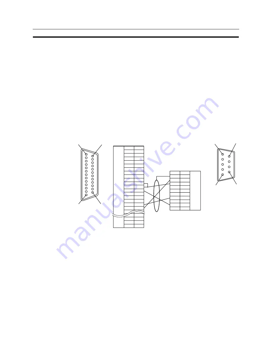
Connecting to the Host’s RS-422A/485 Port
Section 5-2
Wiring when connecting a CS1-series CS1G/H serial communication board, C
series C200HX/HG/HE (–ZE) communication board, or CVM1/CV-series host
link unit
Applicable units:
CS1G-CPU42-E
CS1G-CPU43-E
CS1G-CPU44-E
CS1G-CPU45-E
CS1H-CPU63-E
CS1H-CPU64-E
CS1H-CPU65-E
CS1H-CPU66-E
CS1H-CPU67-E
C200HE-CPU32-(Z)E
C200HE-CPU42-(Z)E
C200HG-CPU33-(Z)E
C200HG-CPU43-(Z)E
C200HG-CPU53-(Z)E
C200HG-CPU63-(Z)E
C200HX-CPU34-(Z)E
C200HX-CPU44-(Z)E
C200HX-CPU54-(Z)E
C200HX-CPU64-(Z)E
C200HX-CPU65-ZE
C200HX-CPU85-ZE
CV500-LK201 (communication port 2)
1
14
13
25
NT31/NT31C side
Shielding wire
(25-pin type)
Abbreviation
FG
−
SD
RD
RS
CS
−
SG
−
TRM
RDB (+)
SDB (+)
−
−
−
SDA (
−
)
RDA (
−
)
−
−
RSB (+)
RSA (
−
)
−
Pin number
Connector
hood
1
2
3
4
5
6
7
8
9
10
11
12
13
14
15
16
−
23
24
25
RS-232C/
422A/485
interface
6
5
9
1
PC side
RS-422A
interface
Pin number
Connector
hood
1
2
3
4
5
6
7
8
9
Abbreviation
FG
SDA
SDB
−
−
−
RDA
−
RDB
−
(9-pin type)
In order to avoid an FG ground loop, do not connect the functional ground of the
NT31/NT31C to the shielding of the RS-422A cable.
Summary of Contents for NT31 Series
Page 1: ...Cat No V043 E1 2 Programmable Terminal NT31 31C OPERATION MANUAL...
Page 2: ...iii NT31 31C Programmable Terminal Operation Manual Produced March 1999...
Page 41: ...30 Before Operating Section 1 5...
Page 75: ...64 Using a Memory Unit NT31 NT31C without V1 Section 3 6...
Page 160: ...149...
Page 174: ...163...
Page 193: ...182...
Page 211: ...200...
Page 235: ...224 c Return to the screen on which screens are specified...
Page 262: ...251...
Page 360: ...349 It is not possible to control a gloval window by touch switch operation...
Page 468: ...457 254 255 0 2 7 1 4 5 3 3 0 0 0 5 9 8 0 3...
Page 476: ...465 Special Functions Section 7 16...
Page 495: ...484 OFF...
Page 610: ...599 Commands Responses Section 9 3...
Page 630: ...619 Examples of Actual Applications of Memory Link Section 10 2...


