


63
CVM1 and CV-series Controller Link Units
Section 4-4
cator on the front of the Unit will light and either communications will stop,
or the INS indicator will not light and you will be unable to participate in the
Network.
3.
The send sequence for the data link areas is determined according to the
sequence of node addresses for automatically set data links.
4.
Assign node addresses consecutively beginning from 01 whenever possi-
ble to minimize Network construction time.
4-4-4
Baud Rates
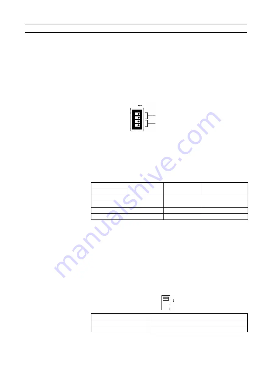
Set the following pins for the baud rate setting (DIP switch).
Note
1.
Always turn OFF the PC’s power before setting the baud rate.
2.
Keep pins 3 and 4 set to OFF. If they are turned ON, internal data may be
erased.
Set the same baud rate for all the nodes on the Network using DIP switch pins
1 and 2 on the front of the Unit. The baud rate is set as shown below.
The maximum transmission distance will also change according to the setting.
Note The factory default setting is shown in bold.
Note Set the same baud rate for all the nodes on the Network. Normal communica-
tion cannot be performed unless the same baud rate is set for all the nodes.
4-4-5
Terminating Resistance
Turn ON the terminating resistance using the switch on the bottom of the Unit
for the Units of both ends of the Network. The terminating resistance is
required at both ends of a Network to absorb unnecessary signals and reduce
noise.
The Controller Link Unit has built-in terminating resistance, which can be con-
nected simply by turning ON the slide switch.
Note
1.
Always turn OFF the PC’s power before setting the terminating resistance
switch.
Pin 3, 4: Not used (must be OFF)
Pin 1, 2: Baud rate
The factory default setting is shown above.
ON
3
2
14
Switch
Baud rate
Maximum
transmission distance
Pin 1
Pin 2
OFF OFF
2 Mbps
500 m
ON
OFF
1 Mbps
800 m
OFF
ON
500 Kbps
1 km
ON
ON
Do not set.
Switch at the front
Terminating resistance
OFF (factory default)
Not connected.
ON connected
ON
Summary of Contents for CVM1-CLK21
Page 2: ......
Page 3: ......
Page 4: ...iv...
Page 6: ...vi...
Page 33: ...17 Application Precautions Section 1 5 2 9 8 2 2 8 5 2...
Page 34: ......
Page 42: ......
Page 66: ......
Page 103: ...87 Setting Data Links Section 5 2 Device Information Setting Data Link Tables...
Page 124: ......
Page 192: ......
Page 280: ......
Page 284: ......
Page 300: ......
Page 304: ......


