background image

Safety Notices

The following general safety precautions must be observed during all phases of operation of this 
instrument. Failure to comply with these precautions or with specific warnings or instructions elsewhere
in this manual violates safety standards of design, manufacture, and intended use of the instrument. 
ODA Technologies assumes no liability for the customer's failure to comply with these requirements.

   Do not block the ventilation openings.

   Do not place the power cord, appliance inlet, or 
   main switch on instrument in difficult way to operate.

General

Do Not Modify the Instrument

   Do not use this product in any manner no

   (provided with a protective earth terminal)   box, product warranty might not be guaranteed. 

   Do not install substitute parts or perform any

   specified by the manufacturer. The prote    unauthorized modification to the product. Return 
   features of this product may be impaired if

   the product to an ODA Sales and Service Office 

   used in a manner not specified in the ope   for service and repair to ensure that safety 

   To minimize shock hazard, the instrumen 

   instructions.

   features are maintained.
   Please be sure to return product with the original 

Ground the Instrument

   packing box when returning. if the product is 

   This product is a Safety Class 1 instrume   damaged during delivery by using other packing

   chassis and cover must be connected to an 
   electrical ground. The instrument must beIn Case of Damage

   Instruments that appear damaged or defective 

   wire firmly connected to an electrical

   unintended operation until they can be repaired by

   (safety ground) at the power outlet. Any    qualified service personnel.

   removing the instrument cover.

   connected to the ac power mains through

   the power cable and any external circuits b

Seperator Arrangement 

Do Not Remove the Instrument Cover
   Only qualified, service-trained personnel w
   are aware of the hazards involved should
   remove instrument covers. Always discon

   Do not use the instrument in fire, flames,    attention to an operating procedure, practice, 
   or explosive areas, and use it indoors.

   or the like that, if not correctly performed or 
   adhered to, could result in personal injury or 
   death. Do not proceed beyond a WARNING 
   notice until the indicated conditions are fully
   understood and met.

in case you replace it on your own will

WARNING

Do Not use in explosive area or outdoors    A WARNING notice denotes a hazard. It calls

Fuses

   of important data. Do not proceed beyond a

   The instrument contains an internal fuse, w

   CAUTION notice until the indicated conditions

   is not customer accessible. You cannot get

   are fully understood and met.

   Verify that all safety precautions are takenCAUTION

   interruption of the protective


   conductor or disconnection of the
   earth terminal will cause a potential

Before Applying Power

    hazard that could result in personal

Ventilation requirements

   applying power. Note the instrument's 

   attention to an operating procedure, practice, or 

   A CAUTION notice denotes a hazard. It calls

   external markings described under 

   the like that, if not correctly performed or adhered

   "Safety Symbols"

   to, could result in damage to the product or loss

   a grounded power cable, with the ground   should be made inoperative and secured against

   Make all connections to the unit before 

Summary of Contents for EX 100-12

Page 1: ...Programmable DC Power Supply User Manual www odacore com EX Series Manual Part NO 019EX 03...

Page 2: ...ould ODA and the user have a separate written agreement with warranty terms covering the material in this document that conflict with these terms the warranty terms in the separate agreement shall con...

Page 3: ...ed operation until they can be repaired by safety ground at the power outlet Any qualified service personnel removing the instrument cover connected to the ac power mains through the power cable and a...

Page 4: ...Safety Symbol...

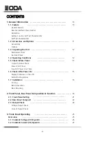
Page 5: ...put AC Power Line Check 1 6 Check After Power On 15 Display Procedure on the LCD Default Setting Values 16 Cooling Bench Operation Rack Mounting 18 2 1 Front Panel Setting 21 22 2 3 Output Check 24 Vo...

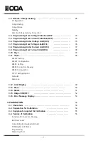
Page 6: ...imit OCL 38 39 40 RS232C Setting RS232C Configuration RS485 Setting RS485 Connection Drawing RS485 Configuration TCP IP Setting Option Delimiter Response 3 12 Limit Display 49 3 13 Store 50 3 14 Recal...

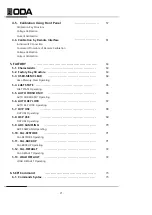
Page 7: ...ory Clear Operating 5 4 LAST STATE 65 LAST STATE Operating 5 5 AUTO CURSOR MV 66 AUTO CURSOR MV Operating 5 6 AUTO KEY LOCK 67 AUTO KEY LOCK Operating 5 7 OVP USE 68 OVP USE Operating 5 8 OCP USE 69 O...

Page 8: ...etting Oprating Comm 74 6 5 Measure Commands 80 6 6 Calibration Commands 81 81 84 7 Error Messages 87 7 1 Operating Error 87 7 2 Hardware Error 87 87 89 7 5 Non volatile Memory Check Error 89 7 6 Inte...

Page 9: ...erating state of voltage current OVP OCP and recall up to 10 Save and confirm up to 10 error messages 19inch Rack Compact Size 600 2 5KW 1U 2 5 5KW 2U 5 10KW 4U High efficient output of 80 90 Characte...

Page 10: ...ries and Options Accessories AC input cord 1pc 1 5meter Spare Fuse 1pcs User s Manual QR Code Option TCP IP communication module RS232C Cable 1M 2M 4M RS485 Cable 2 4 8 Channel 1M 2M 4M 10M AC Input C...

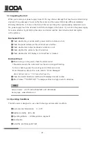
Page 11: ...rminals are broken or not Check whether the cabinet is free of scratches Check whether the LDC display is not scratched or cracked Electrical Check When turning on the power check the alarm sound If t...

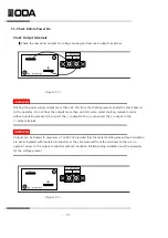
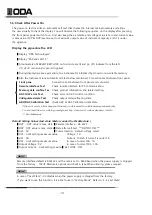
Page 12: ...60 Vdc when metal shorting material or wire without insulation are used to connect the output to the sense and the output to the sense terminals WARNING Outputs can be floated to maximum of 240 Vdc p...

Page 13: ...m a nominal 198 242 V single phase AC power source at 47 to 63 Hz AC100V 110V 115V 230V input power is optional Refer to chapter 1 2 Accessories Options In order to prevent the instrument severe damag...

Page 14: ...H W error Test Check error on ADC control condition UnRegulated state Test Check output voltage floating state ADC DAC Calibration Test check ADC DAC Calibration data state If the error occurs alarm...

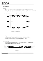
Page 15: ...el and exhausting it out the sides Using an ODA rack mount will not impede the flow of air Figure 1 4 Bottom view Bench Operation Your power supply must be installed in a location that allows sufficie...

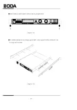
Page 16: ...Fasten between rack bracket and rack case by using fastener it is very east to install 17 Figure 1 8 To install instruments in a sliding support shelf order support shelf and slide kit and Figure 1 6...

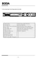
Page 17: ...ay Key 4 16 Protection setting and Front panel Lock Key 5 17 Voltage Current setting value Display Key 6 18 Save value or Calibration Key 7 19 Recall or Factory Key 8 9 10 11 12 Volt Cursor or Menu Ch...

Page 18: ...output on state LED is turned off 6 Key Lock Lamp If Key lock lamp is turned on front panel keys are not working 7 Remote Interface Lamp When received the remote control signal from PC PLC and etc it...

Page 19: ...vel and clears the over voltage condition Also press this key for 1sec you can lock front panel operating with lighting LOCK lamp Press agaoin this key for 1 sec clear the lock key 17 Volt Curr Settin...

Page 20: ...sing 5 In order to increase the volt curr limit value turn the encoder clockwise In order to decrease the volt curr limit value turn the encoder counter clockwise 6 Confirm the change of setting value...

Page 21: ...nput connector Input terminal of negative output voltage sensing For more informaiton refer to 3 3 Remote Voltage Sensing 4 Voltage Sensing Input connector Input terminal of positive output voltage se...

Page 22: ...ss So you can control power supply anywherer in world 11 RS485 TERMINAL When use RS485 communication in parallel connection it is a switch which can be used for terminating resistance 12 AC Input Fuse...

Page 23: ...D display real voltage value and DVM annunciator Current Output Check The following steps check basic current functions with a short across the power supply s output 1 Turn on the power supply 2 The o...

Page 24: ...over voltage protection 5 Programming Over Current Protection OCP Explain about the programming of over current protection 6 Programming Under Voltage Limit UVL Explain about the programming of under...

Page 25: ...order to set the current value use the right cursor key and encoder knob Under the protection OVP UVL OVL setting state current ca nnot be over protection level If the voltage value is over the protec...

Page 26: ...he current value use the right cursor key and encoder knob Under the protection OVP UVL OVL setting state current ca nnot be over protection level If the voltage value is over the protect ion setting...

Page 27: ...must be added to the load voltage to calculate maximum output voltage The performance specifications are not guaranteed when the maximum output voltage is exceeded If the excessive demand on the powe...

Page 28: ...ower supply s programming feedback loop accidental open connections of sense or load leads during remote sensing operation Reminder never connect the load leads to sense lead terminal Connecting Remot...

Page 29: ...ge Set the trip level Note that you cannot set the trip levels to lower than current real output volt in order to prevent the operator s malfunction occurring After set the trip levels that you want p...

Page 30: ...OVP level Second Maybe the DUT is like a coil motor and as like a source that make an in rush current To avoid this a UF diode must be connected in series with the output as shown below Third In case...

Page 31: ...ed to change the level press the Protection key LCD Display CHANGED After displayed above message return to before state that tripped OVP Related Remote Interface Command VOLT OVP voltage VOLT OVP VOL...

Page 32: ...SET 88 00a Move the under bar cursor location where you want to change Set the trip level Note that you cannot set the trip levels to lower than current real output Voltage in order to prevent the op...

Page 33: ...off the OCP function Enter the Factory mode and move to 6 OCP USE and then disable this function When occurs OCP trip OCP TRIPPED message appears on the display In order to clear tripped OCP increase...

Page 34: ...the UVL level LCD Display PROTECT 1 OVP Move to the UVL menu by using right cursor key LCD Display PROTECT 3 uvl Press the Protection key one more time at the 3 uvl state LCD Display UVL SET 00 00v Mo...

Page 35: ...n other to set the OVL level LCD Display PROTECT 1 OVP Move to the OVL menu by using right cursor key LCD Display PROTECT 4 Ovl Press the Protection key one more time at the 3 ovl state LCD Display OV...

Page 36: ...the UCL level LCD Display PROTECT 1 OVP Move to the CVL menu by using right cursor key LCD Display PROTECT 5 uCl Press the Protection key one more time at the 5 ucl state LCD Display UCL SET 00 00A Mo...

Page 37: ...in other to set the OCL level LCD Display PROTECT 1 OVP Move to the OCL menu by using right cursor key LCD Display PROTECT 6 Ocl Press the Protection key one more time at the 6 OCL state LCD Display O...

Page 38: ...ocking In order to unlock the front panel operating press the Protection Key Lock key key during 3 seconds over LOCK annunciator is off and unlocking Related Remote Interface Command KEYL OFF ON KEYL...

Page 39: ...k Press the Protection key and unlock RS232C Setting RS232C setting procedure Turn on the power supply After turned on check the power supply displays OUTPUT OFF Mode Press I O key in order to set RS2...

Page 40: ...Below is connection drawing of cross cable of female type proceed as follows Refer to chapter 1 2 Accessories Option and then you ca n choose the communication cable length or other using method Figu...

Page 41: ...ay br 1 9600 bps Or it may differ depending on previous state Baud rate is consist of 9600 19200 38400 57600 115200 and 230400bps You must match between remote interface and device s baud rate Press I...

Page 42: ...4 3 2 1 8 7 6 5 4 3 2 1 RS485 1 2 3 4 5 6 7 8 GROUND DATA RS485 NOT CONNECTED DATA RS485 RS232C RS485 RS485 NOT CONNECTED DATA RS485 RX RS232C DATA RS485 GROUND DATA RS485 TX RS232C DATA RS485 NOT CO...

Page 43: ...configuration In order to connect between RS485 line and remote device as like PC or PLC you need extra wire that below figure connection Refer to Figure 3 5 Figure 3 5 Figure 3 5 44 485 to 232 Conve...

Page 44: ...the display LCD Display I O 4 tcp ip Press the I O Local key in order to set the TCP IP LCD Display 1 Static Or it may differ depending on previous state Setting method is two type The one is fixed IP...

Page 45: ...ethod is TCP IP DHCP setting method Turn on the power supply After turned on check the power supply displays OUTPUT OFF Mode Press I O key in other to set TCP IP interface LCD Display I O 1 RS232C Or...

Page 46: ...eriod of time after appeared Time Out Error message automatically quit form menu Check IP address Turn on the power supply After turned on check the power supply displays OUTPUT OFF Mode Press I O key...

Page 47: ...After appear delimiter cr message press the IO Local key after then appear SAVED message LCD Display SAVED Response You are able to have the response when you send the commennd to power supply When s...

Page 48: ...D Display 00 00V 88 00A By using encoder knob you can set the voltage or current After finished to set press the Limit Display key And return to previous state LCD Display output off Limit Display at...

Page 49: ...Turn the encoder knob to specify the memory location among 01 10 For examples turn the knob to the right to specify the memory location 2 LCD Display STORE NO 02 In order to store in your selected me...

Page 50: ...state LCD Display RECALL NO 01 Choose the storage location number that you want to apply by using encoder knob For examples if you want to apply No 02 state turn to right one click LCD Display RECALL...

Page 51: ...ey In order to enable output off press the OUTPUT ON OFF key once more Related Remote Interface Command OUTP OFF ON OUTP Apply Check output state and in case output is off the method of changing to ou...

Page 52: ...ress the ERROR key during 3 seconds If no error appears next display and return to previous state LCD Display NO ERROR Turn off ERR lamp If exists error appears next display LCD Display ERROR NO 200 I...

Page 53: ...manently Be able to restore and backup the calibration data Easy to calibrate by comparing between calibration equipment and power supply at a one to one method 4 2 Preparation for Calibration Use mor...

Page 54: ...ar It is fine to use the general load resistor instead of electronic load Figure 4 1 Using article 0 001 0 01 Measuring ripple noise Current monitoring 55 Oscilloscope Agilent 34401A Resolution 0 1 mV...

Page 55: ...urrent Monitoring Resistor shunt Normally current measuring instruments is not suitable high current capacty s measuring so generally use current monitoring resistor Select shunt that TCR is below 10p...

Page 56: ...me you must connect the load resistor to A point of figure 4 3 and you must connect the measuring instrument at the B point of fighre 4 3 V Sensign connecting hole Figure 4 3 4 5 Using Front Panel Cal...

Page 57: ...r 5 minute Wait until DVM display voltage becomes stable Enters a voltage value that you obtained by reading an external DVM meter If the value is 151 9mV enters as following below LCD Display V LOW 0...

Page 58: ...n current calibration connect the power supply output terminal and electronic load and connect the power supply output terminal and shunt lead for current monitoring and then connect shunt s the other...

Page 59: ...cursor key and press the Calibration key LCD Display a high 61 00a Display current can be different Wait for 5 minute Wait until DVM display voltage becomes stable Calculate the current when DVM disp...

Page 60: ...commands as next order if occurs the errors remote calibration is cancelled If error is occurred you must restart remote calibration Voltage Calibraton Send the OFF command to electronic load Send min...

Page 61: ...ere After waiteing for minimum 5 minutes more measures DVM s voltage that is connected with current monitoring resistor Send calculated current value that caculated by current value calculating progra...

Page 62: ...pply power off Be able to change to minimum value of voltage current value automatically if you are not use the power supply for long time Be able to lock the power supply s front panel if you are not...

Page 63: ...evel OCP setting maximum value UVL Level 0V OVL Level Limit maximum value UCL Level 0A OCL Level Limit maximum value Output Mode OFF USER MEM CLEAR Operating Power switch on in a pessing FACTORY key P...

Page 64: ...turn off fully If you set the voltage 12 00V current 40 00A and turn off the power and turn on the power after run the self test recalls befor appears 12 00V 00 00A and output state is on LAST STATE...

Page 65: ...nable AUTO CURSOR MV mode AUTO CURSOR MV Moving Operating Power switch on in a pessing FACTORY key Power switch ON When appearing 1 user mem clear message release FACTORY key Enter to 3 AUTO CURSOR MV...

Page 66: ...TO KEY LOCK mode ENABLE Enable AUTO KEY LOCK mode AUTO KEY LOCK Operating Power switch on in a pessing FACTORY key Power switch ON When appearing 1 user mem clear message release FACTORY key Enter to...

Page 67: ...USE mode OVP USE operating Power switch on in a pressing FACTORY key in a pessing Power switch ON When appearing 1 user mem clear message Release release FACTORY key Enter to 5 OVP USE mode by using c...

Page 68: ...USE mode OCP USE operating Power switch on in a pressing FACTORY key in a pessing Power switch ON When appearing 1 user mem clear message release FACTORY key Release Enter to 6 OCP USE mode by using c...

Page 69: ...trument default value 50Hz Measures voltage current at every 20ms 100Hz Measures voltage current at every 10ms 300Hz Measures voltage current at every 3 3ms 1 3KHz Measures voltage current at every 77...

Page 70: ...r to restore press the FACTORY key one more time LCD Display 5 11 CAL BACKUP Recommended calibration interval is 6 monthes and in order to precision of the power supply you must calibrate this unit at...

Page 71: ...r to restore press the FACTORY key one more time LCD Display 5 13 LOAD DEFAULD This function is to return to default value that shipped the unit from factory You can erase setting and changing all val...

Page 72: ...kip it You can not skip the parameter in braces Triangle brackets indicate that you must substitute a value or a code examples MIN MAX for the enclosed parameter A vertical bar separates one of two or...

Page 73: ...ACT AUTO CUR DIS ENA FACT AUTO CUR FACT AUTO LOC DIS ENA FACT AUTO LOC FACT OVP DIS ENA FACT OVP FACT OCP DIS ENA FACT OCP FACT ADC 5 20 50 100 300 1300 FACT ADC FACT LOAD DEF SYST BEEP SYST ERR SYST...

Page 74: ...mmand programs the immediate vlotage level of the power supply The immediate level is the voltage value of the output terminals This command also increases or decreases the immediate voltage level usi...

Page 75: ...s query returns a 1 if the overvoltage protection circuit is tripped and not cleared or a 0 if not tripped Return value 0 not tripped state 1 OVP Trip state and cut the output return value 1 VOLT OVP...

Page 76: ...turns the under voltage limit value presently programmed Return value numeric value return value 15 00 CURR current UP DOWN This command programs the immediate currenr level of the power supply The im...

Page 77: ...OVP Level to 5 2A CURR OCP This query returns the overcurrent protection trip level presently programmed Return value numeric value ex curr ocp return value 5 20 CURR OCP TRIP This query returns a 1 i...

Page 78: ...it value presently programmed Return value numeric value ex curr ucl return value 5 00 CURR OCL numeric value This command sets the over current limit level numeric value Currently setting value mixim...

Page 79: ...eturn value p 6 5 Measure Commands Measure commands measure the output voltage or current MEASure commands acquire new data before returning the reading Also you don t need DVM Digital Volt Meter and...

Page 80: ...URR current MIN MAX This command is for current calibration Be careful calibration procedure Refer to 4 6 Remote Interface Calibration current This command save the calibration measuring current value...

Page 81: ...he power supply s cursor location go down to minimum changing unit automatically when you set the AUTO CURSOR MV mode is enable DIS Disable AUTO CURSOR MV mode ENA Enable AUTO CURSOR MV mode Disable A...

Page 82: ...es voltage current at every 5 times 1sec measure very precise value 20 Measures voltage current at every 20 times 1sec measure very precise value 50 Measures voltage current at every 50 times 1sec mea...

Page 83: ...first occurred error at first If check the error automatically erase the comfirmed error and there are no error you can receive 0 value No error Message Return value error number message ex syst err r...

Page 84: ...command is confirming the power supply s properties You will receive 3 kinds properties Return value ODA Technologies EX Series 1 3 1 3 1 2 First Manufacturer Second Products model Third Products det...

Page 85: ...supply Following is initializing contents Output OFF Voltage Limit 0V Current Limit Maximum current value of the power supply OVP Maximum OVP value of the power supply OCP Maximum OCP value of the po...

Page 86: ...erating failed It appears when circuit of ADC part is out of order 202 Front panel operating failed It appears when front panel does not respose 255 Error not define It appears when unknown error occu...

Page 87: ...max command without Value of current Min calibration operating Procedure Min VALUE MAX VALUE 29 Invalid min value use under curr After sent the command of current Min value and then you sent the value...

Page 88: ...s the error of setting available voltage value 81 Memory limit curr error It means the error of setting available current value 82 Memory max volt error It means the error of the power supply s maximu...

Page 89: ...d the command or it may not be a valid command If you are using the short form of the command The power supply just receive Volt or Voltage You must revise to volt 10 220 No execution The power supply...

Page 90: ...anted but are descriptions of performance determined either by design or testing The service guide contains procedures for verifying the performance specifications Accuracy specifications are after an...

Page 91: ...92...

Page 92: ...93...

Page 93: ...uate air circulation Do not place the heavy things on the power supply Avoid the electric magnetic field as motor and etc Do not allow any foreign matter such as metal or inflammable substance to get...

Page 94: ...62 Bupyeong daero 329beon gil Bupyeong gu Incheon city 403 858 Korea TEL 82 2 1800 8644 FAX 82 32 715 5456 www odacore com sales2 odacore com ODA TECHNOLOGIES CO LTD...

Reviews: