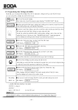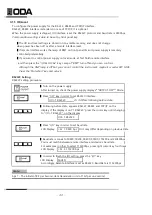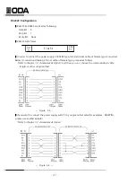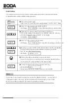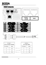
3-3. Remote Voltage Sensing
Remote voltage sensing is used to maintain regulation at the load and reduce the degradation of regulation
that would occur due to the voltage drop in the leads between the power supply and the load.
By connecting the power supply for remote voltage sensing, voltage is sensed at the load rather than
at the power supply’s output terminals. This will allow the power supply to automatically compensate for
the voltage drop in applications with long lead lengths as well as to accurately read back the voltage directly
across the load. When the power supply is connected for remote sensing, the OVP circuit senses the voltage
at the sensing points (load) and not the output terminals.
CV Regulation
The voltage load regulation specification in chapter 8 applies at the output terminals of the power supply.
When remote sensing, add 5 mV to this specification for each 1 V drop between the positive sensing point
and (+) output termina due to the change in load current. Because the sense leads are part of
the power supply’s feedback path, keep the resistance of the sense leads at or below 0.5 per lead
to maintain the above specified performance.
Output Rating
The rated output voltage and current specifications apply at the output terminals of the power supply
that you purchased product's capacity. With remote sensing, any voltage dropped in the load leads must
be added to the load voltage to calculate maximum output voltage.
The performance specifications are not guaranteed when the maximum output voltage is exceeded.
If the excessive demand on the power supply forces the power supply to lose regulation.
Also voltage remote sensing value is exceeded 1V per one wire, the power supply can be
under unregulated state regardless of maximum output voltage.
What is Unregulated state? If the power supply should go into a mode of operation that is neither CV or CC
the power supply is unregulated. In this mode the output is not predictable. The unregulated condition may be
the result of the ac line voltage below the specifications. The unregulated condition may occur momentarily.
For example when the output is programmed for a large voltage step; the output capacitor or a large capacitive load
will charge up at the current limit setting. During the ramp up of the output voltage the power supply will be
in the unregulated mode. During the transition from CV to CC as when the output is shorted, the unregulated state
may occur briefly during the transition.
Output Noise
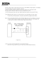
Any noise picked up on the sense leads also appears at the output of the power supply and may
adversely affect the voltage load regulation. Refer to <Figure. 3-1>.
▌
Twist the sense leads to minimize external noise pickup.
▌
Run the sense leads parallel and close to the load leads.
▌
In noisy environments it may be necessary to shield the sense leads.
▌
Ground the shield at the power supply end only
▌
About load leads and sense leads, connect in the nearest distance.
Note
- 28 -
Summary of Contents for EX 100-12
Page 1: ...Programmable DC Power Supply User Manual www odacore com EX Series Manual Part NO 019EX 03...
Page 4: ...Safety Symbol...
Page 91: ...92...
Page 92: ...93...


