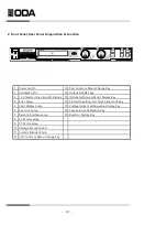
2-2. Rear Panel Composition
1
9 RS-485 Interface Port
2
10 TCP/IP Port(option)
3 - Voltage Sensing Input connector
11 RS485 TERMINAL
4 + Voltage Sensing Input connector 12 AC Input Fuse
5
13 Ex Series Option Port
6
14 Analog Input & Output Calibration Port
7
15 Earth Ground Connection Screw
8 RS-232C Interface Port
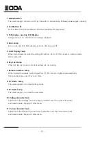
1. - Output bus bars
Negative DC power output bus bar of power supply
2. + Output Bus Bars
Positive DC power output bus bar of power supply
3. - Voltage Sensing Input connector
Input terminal of negative output voltage sensing. For more informaiton, refer to 3-3. Remote
Voltage Sensing
4. + Voltage Sensing Input connector
Input terminal of positive output voltage sensing. For more informaiton, refer to 3-3. Remote
5. Ventilation Slit
A fan cools the power supply by drawing air through the front panel air slit and side air slit and
exhausting it out the rear air slit.
6. AC Power Input Connector
AC Power Input Connector. Normailly, 220V/50-60Hz AC input is standard. But you can order
other input AC power. Refer to 2-2. Accessories and Options
- 22 -
Earth Ground
+ Output bus bars
AC Power Input Connector
- Output bus bars
Ventilation Slit
Summary of Contents for EX 100-12
Page 1: ...Programmable DC Power Supply User Manual www odacore com EX Series Manual Part NO 019EX 03...
Page 4: ...Safety Symbol...
Page 91: ...92...
Page 92: ...93...

