


Operation OEM6 Cards and Enclosure
Chapter 4
OEM6 Family Installation and Operation User Manual Rev 7
61
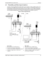
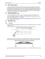
Transfer FINE Time from a Fine Clock to a Warm Clock GPS Receiver
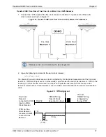
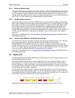
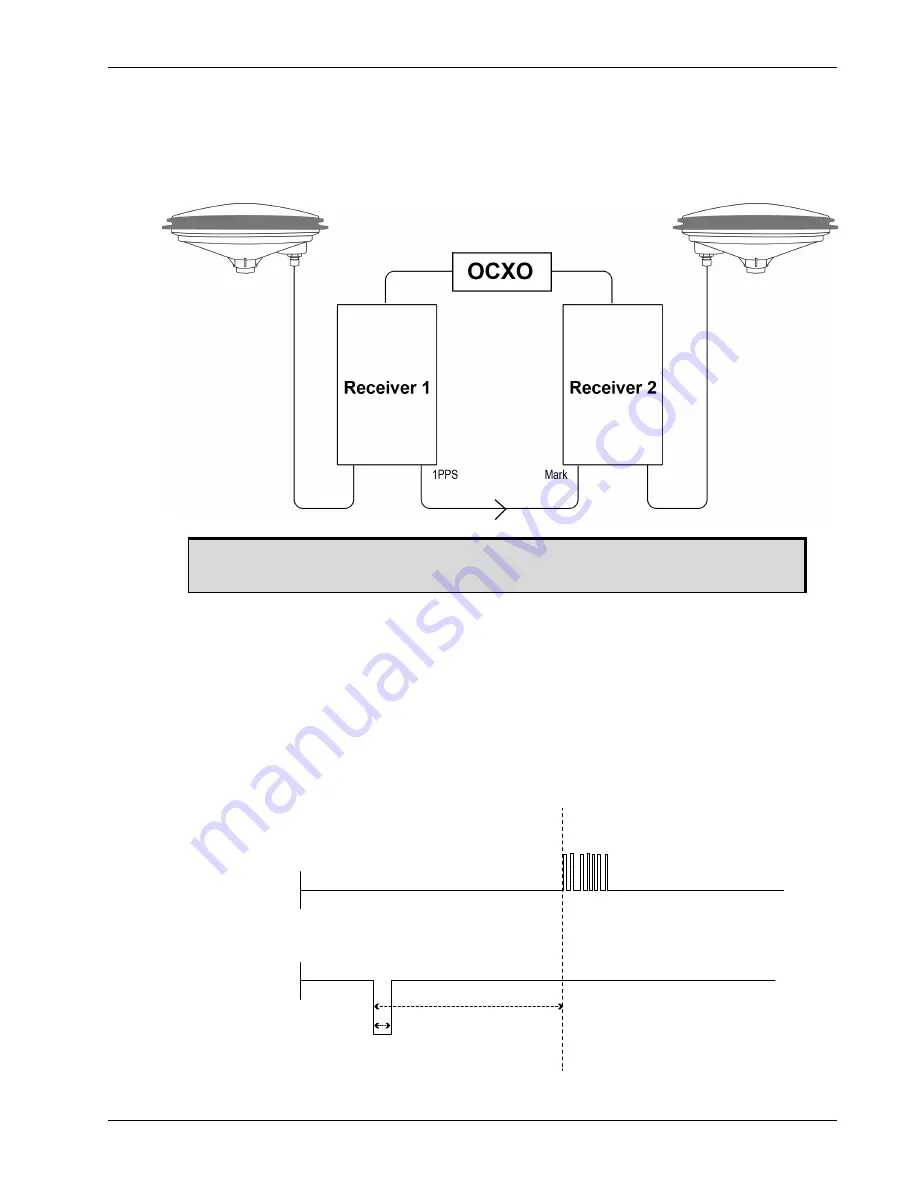
1. Connect the 1 PPS signal of the fine clock receiver to the Mark 1 input (Event1) of the warm
clock receiver as shown in
.
Figure 21: Transfer FINE Time from Fine Clock to Warm Clock Receiver
2. Issue the following command to the warm clock receiver:
adjust1pps mark
The phase of the warm clock receiver clock is adjusted by the fractional measurement of the fine clock
receiver’s 1 PPS mark input event. In other words, it synchronizes the warm clock receiver’s 1 PPS to the
incoming 1 PPS of the fine clock receiver. It does not adjust the one second TOW counter or the
receiver’s week number. This procedure is used to make small corrections to the warm clock receiver’s
clock.
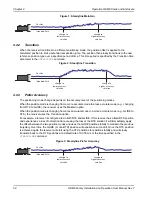
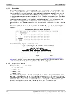
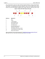
Figure 22: 1 PPS Alignment
If Receiver 2 is not in coarsetime, the input is ignored.
Fine Clock
Warm Clock
Fine Clock
Receiver
connected to COM
Input on Warm
Clock Receiver
1PPS on Fine
Clock Receiver
connected to MK1|
on Warm Clock
Receiver
RS-232
TTL
10 ms
1PPS IN
(1 ms)
TIMESYNC log
transmit time is
dependant on baud
The next
TIMESYNC log
is triggered by
the next PPS