170
OEM6 Family Installation and Operation User Manual Rev 7
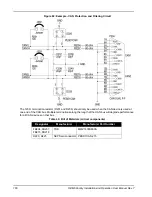
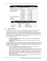
Table 42: Recommended Ethernet Transformer Characteristics
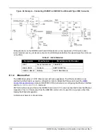
Table 43:
Bill of Materials (Critical Components Only)
E.1.9
System Performance
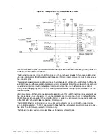
The OEM638 receiver (as with any precision GNSS product) is an extremely sensitive radio receiver.
Typical GNSS signal levels are on the order of -145 dBm. Spurious emissions from digital logic
(especially a microprocessor) or a nearby radio transmitter can easily meet the appropriate EU or FCC
emission limits and still have emissions several orders of magnitude above the level of the GNSS carrier.
These emissions may desensitize the GNSS receiver and lead to performance degradation (low carrier
to noise ratios, position accuracy or loss of lock in extreme cases).
There are two bands of interest:
•
Low Band (1165 MHz to 1300 MHz): contains Galileo E5A, GPS L5, Galileo E5B, BeiDou B2,
GPS L2 and GLONASS L2.
•
High Band (1525 MHz to 1613 MHz): contains Omnistar, BeiDou B1,Galileo E1, GPS L1 and
GLONASS L1
NovAtel and the OEM638 development team have put significant effort into mitigating RF interference on
the GNSS card itself. However, if an emission (fundamental or harmonic) from equipment co-located with
the GNSS receiver or antenna falls into one of these bands, there are a few things that integrators can do
to ensure good system performance:
•
Place radio transmitters and their associated antennas at least one meter from the GNSS
antenna and OEM638 card (for example, a cellular radio antenna).
•
Provision for RF shielding over all high-speed digital logic circuitry (even if the design meets the
required emissions regulations). A CPU operating at 400 MHz will produce an emission at 1200
MHz (3
rd
harmonic) and another at 1600 MHz (4
th
harmonic)—the emissions may be strong
enough to affect the GNSS system’s performance as both signals are very close to (or inside of)
the GNSS reserved spectrum. Similar provisions should be made for any RF circuitry near the
GNSS receiver or antenna.
•
Run the OEM638 coaxial RF cable away from high speed digital logic, other radio sections and
high current nets (as in switching power supplies).
Parameter
Value
Test Condition
Turns Ratio
1 CT : 1 CT ±3%
Open-cct inductance (min)
350 uH
100 mV, 100 kHz, 8 mA
Insertion Loss (max)
1.0 dB (max)
1 - 100 MHz
Return Loss (min)
-18 dB (min)
1 - 10 MHz
-16 dB (min)
10 - 30 MHz
-12 dB (min)
30 - 60 MHz
-10 dB (min)
60 - 80 MHz
Common-Mode Rejection
-30 dB (min)
1 - 100 MHz
Crosstalk
-30 dB (min)
1 – 100 MHz
HIPOT (min)
1500 Vrms
For 1 minute
Designator
Manufacturer
Manufacturer Part Number
J403
Wurth Elektronik
Midcom
7499211121A
7499211121
D405, D406
On Semi
ESD7L5.0DT5G
FB403
MuRata
BLM18PG121SN1D

