38
OEM6 Family Installation and Operation User Manual Rev 7
Chapter 3
Installation FlexPak6
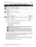
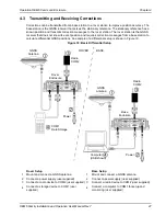
Figure 15: FlexPak6 Installation
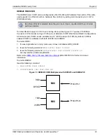
Refer to Appendix C for cabling details:
•
•
Figure 71, I/O DB-HD15 Strobe Port Cable
•
Figure 72, Straight Through Serial Cable
•
•
Figure 74, 12 V Power Accessory Cable
FPk6
The FlexPak6 is RS-232/RS-422 selectable through pin 9 of the I/O port, see
FlexPak6 I/O Port Pin-Out Descriptions
for details.
FPk6
The FlexPak6 enclosure is a Data Terminal Equipment (DTE) so that TXD and RTS are
outputs while RXD and CTS are inputs. A null modem cable, supplied with the receiver, is
required to connect to another DTE like a terminal or a computer, while a straight through
cable is used to connect to another receiver.
COM1
I/O
COM2
Using a coaxial cable,
connect the antenna to
the port, which is
found on the front face
of the FlexPak6.
Connect the 12 V power
cable connector to the
port. Line up the red mark
on the power cable
connector with the red
mark on the receiver’s
Power port and insert
power cable.
Connect the
COM1
or
USB
port on the receiver to the
USB
or
serial port of the computer. If using a USB connection, install the
USB drivers available from
.


