Nortel Networks Confidential
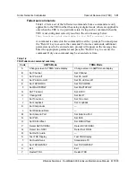
Transmit Receive Unit (TRU)
1-25
Wireless Solutions
DualMode 800 Enclosure Maintenance Manual
MTX08
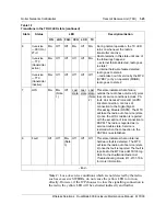
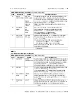
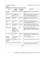
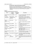
Note 1: Loss-of-service conditions which are not detected by the radio,
such as excessive SWERRs, do not cause the yellow LED to turn on
directly. However, if the ICP chooses to close the signalling connection to
the radio, the yellow LED will be activated indirectly and further
6
In-service
—DCCH or
2T+C
On
Off
Off
On
Off
On
During normal operation, the TX LED
turns on whenever the radio’s
transmitter is active.
Radio remains in this state until one of
the followings happens:
—external failure detected, radio goes
to state 7
—internal hardware failure detected,
radio goes to state 8
—radio taken out of service by the MTX
(SYBSY) or by an operator (MANB),
radio goes to state 2
In-service
—TTC
(transmitter
active)
On
Off
Off
Off
Off
On
In-service
—TTC
(transmitter
inactive)
On
Off
Off
Off
Off
Off
7
LOS
On
On
(Note
1)
Off
Last
state
Last
state
Last
state
(Note
2)
This state indicates that a failure
outside the radio has occurred. Typical
loss of service conditions include: PA
fault, Link Access Protocol-D (LAPD)
link disconnection, or a loss of
connection to the Digital Signal
Processing Module (DSPM). The MTX
will take the radio out of service (state
2) once the LOS condition is reported
with the exception of loss connection to
DSPM. The radio is reported as in-
service trouble state. Service is
restored when the connection to the
DSPM is re-established.
8
Fault
Off
Off
On
(Note
3)
Off
Off
Off
This state indicates that an internal
hardware fault is detected. The MTX
will take the radio out of service (state
2) once the fault is reported. The fault is
reported to the MTX as an MTX105 log.
Refer to the
DualMode Radio Unit
Troubleshooting Guide
, 411-2131-166,
for more information.
- End -
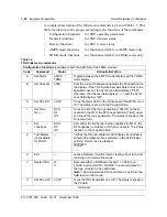
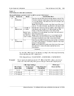
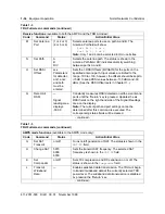
Table 1-1
Transitions in the TRU3 LED state (continued)
State
Status
LED
Description/Action
ON
LOS FAIL CCH LCR
TX
Summary of Contents for DualMode 800
Page 2: ......
Page 4: ......
Page 6: ...vi Publication history Nortel Networks Confidential 411 2051 500 Draft 00 01 November 1999...
Page 82: ...2 20 Periodic maintenance 411 2051 500 Draft 00 01 November 1999...
Page 90: ...3 8 Test equipment and precautions 411 2051 500 Draft 00 01 November 1999...
Page 100: ...5 6 Master Oscillator tests 411 2051 500 Draft 00 01 November 1999...
Page 106: ...6 6 Antenna and transmission line tests 411 2051 500 Draft 00 01 November 1999...
Page 116: ...8 4 Alarm Control Unit ACU tests 411 2051 500 Draft 00 01 November 1999...
Page 138: ...10 2 ICRM tests 411 2051 500 Draft 00 01 November 1999...
Page 200: ...12 10 Enclosure maintenance 411 2051 500 Draft 00 01 November 1999...
Page 208: ...A 8 Appendix A Frequency table 411 2051 500 Draft 00 01 November 1999...
Page 215: ......

