8-2
Alarm Control Unit (ACU) tests
411-2051-500
Draft
00.01
November 1999
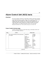
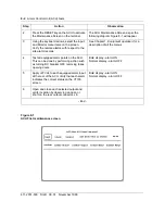
Figure 8-1
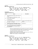
ACU First maintenance screen
2
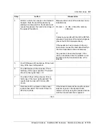
Press the RESET key on the ACU to activate
the Maintenance Screen on the terminal.
The ACU Maintenance Screen as per the
following diagram Figure 8-1 will appear.
3
Using the keyboard arrows, select the Input
and Monitor menu items on the screen.
Verify the remote alarms with respect to the
site alarm records.
See Chapter 1,
Equipment operation
, for a
description of all the menus.
4
Test all equipped alarm points on the ACU.
This can be done by performing action such
as turning DC breaker OFF, removing fuses,
opening doors.
Bold display - alarm ON
Normal display - alarm OFF
5
Apply +27 Vdc to each equipped alarm input
at the rear of the ACU. Verify that each alarm
indicates the correct status on the VT100
screen.
Bold display - alarm ON
Normal display - alarm OFF
6
Open and close each selected output and
verify its action by observing an open or
short on the rear output connector, J8.
- End -
Step
Action
Observation
Summary of Contents for DualMode 800
Page 2: ......
Page 4: ......
Page 6: ...vi Publication history Nortel Networks Confidential 411 2051 500 Draft 00 01 November 1999...
Page 82: ...2 20 Periodic maintenance 411 2051 500 Draft 00 01 November 1999...
Page 90: ...3 8 Test equipment and precautions 411 2051 500 Draft 00 01 November 1999...
Page 100: ...5 6 Master Oscillator tests 411 2051 500 Draft 00 01 November 1999...
Page 106: ...6 6 Antenna and transmission line tests 411 2051 500 Draft 00 01 November 1999...
Page 116: ...8 4 Alarm Control Unit ACU tests 411 2051 500 Draft 00 01 November 1999...
Page 138: ...10 2 ICRM tests 411 2051 500 Draft 00 01 November 1999...
Page 200: ...12 10 Enclosure maintenance 411 2051 500 Draft 00 01 November 1999...
Page 208: ...A 8 Appendix A Frequency table 411 2051 500 Draft 00 01 November 1999...
Page 215: ......


