52
Chapter 9
Adding markers to a measurement
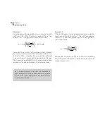
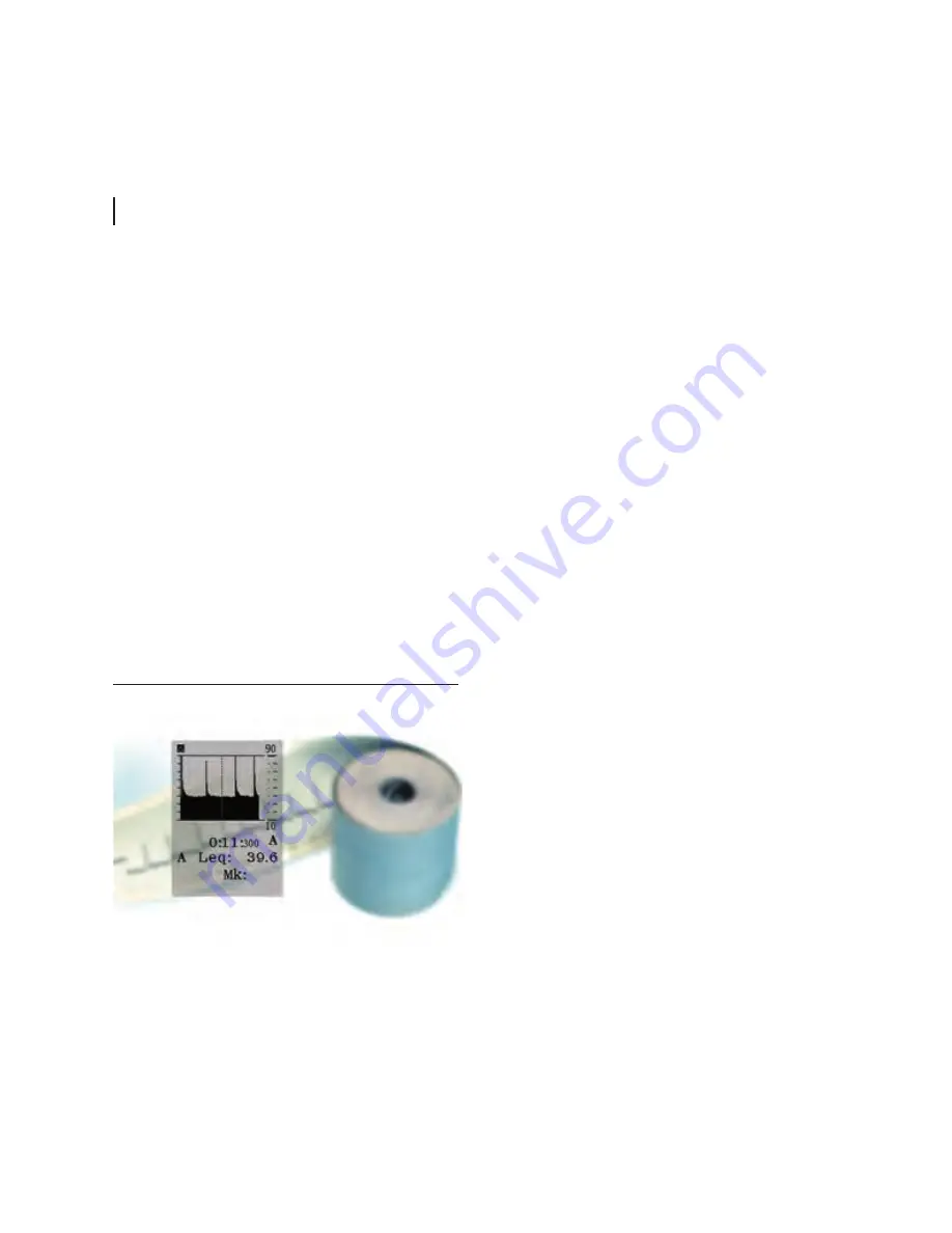
What were these impulses caused by?
Adding markers to a
measurement
Have you ever made a measurement where you later
found out that you desperately need to identify the
cause of the level?
Enter
source coding
. With the enhanced profile
option (optional extension 7) you may tag or code
sources as they happen. A one digit code (which
appears in the display as 1~4) is entered to later
serve as an identification of the type of noise. This
can also be referred to as adding a marker to the
measurement.
Example:
In a traffic noise measurement a bus pass-
ing may be identified by the digit “1”, while trucks may
be identified by “2”, unexpected vehicles by “3” etc.
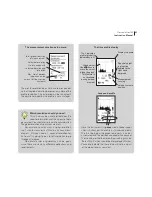
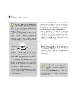
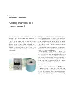
In the profile display the markers appear as dots or
lines below the graph. If you move the time cursor onto
such a dot, the marker type (i.e. its number) will appear
in the display.
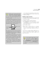
During a measurement, adding any of the markers
“1”, “2” and “3” will assign the corresponding marker
number to the current period only.
When you press marker number “4”, however, the
marker will stay on until the key is pressed again. The
marker will therefore be assigned to the current period
plus all consecutive periods until the marker again is
deactivated. This marker type is often referred to as a
toggle marker, as opposed to the single marker which
is the other type. A typical application for a toggle
marker is to mark out intervals of particular interest.
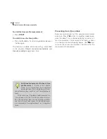
The keys to use
The keys used to enter the markers are
(marker
1),
MODE
(marker 2),
CAL
(marker 3) and
EXIT
(marker 4) since these keys are the lower most keys of
the front panel and thus easy to reach during a meas-
urement. None of these keys are used for other things
during a measurement either.
Summary of Contents for nor140
Page 4: ......
Page 16: ......
Page 17: ...nor140 SOUND ANALYSER ...
Page 18: ......
Page 212: ...194 ...
Page 218: ......


