


13
Norsonic Nor140
Instruction Manual
13
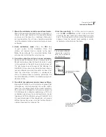
Screw only
finger tight!
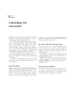
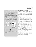
Microphone
preamplifier
Preamplifier socket
Front plate
Display
SD-card
Multifunction
socket
Keyboard
Microphone
cartridge
Default cartridge is
designed for 200 V
polarisation volt-
age, but this can be
switched off.
To fasten
preamplifier, screw
it on here
Instrument body
AC-out
External power
input socket
USB
RPM input
Battery
compartment
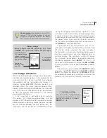
Clock
The date and time setting. Press
SETUP
>
1
(Instr.) >
3
(Clock)
to produce this dialogue box.
Marks on the lower line of the display
You may find the following marks on the lower line:
dB
The signal strength is indicated as a level in
decibel. The reference level is normally 20 µPa
for sound pressure levels.
EU
Engineering unit: The signal strength is indicated
in a generic linear unit. The actual unit could
be voltage referring to the voltage on the input
terminal or ms-2 if an accelerometer is connected
to the input.
#
Num
al keyboard. The number printed on the
keys are entered if you press one of the keys on
the keyboard
E
A numeric value has been entered. The
instrument expects that you press
ENTER
to
confirm the number.
N/H
Indicates
N
ormal or
H
igh measurement range.
(Polarization voltage dependant.)
?
A key is pressed that the instrument does not
understand.
Additionally there are marks indicating the applied
corrections found on the lower line of the display:
R
Random incidence correction ON
W
Wind screen correction ON
G
Preamplifier correction ON
S
Self-noise correction ON
E
Polarization voltage off - Electret microphone
Summary of Contents for nor140
Page 4: ......
Page 16: ......
Page 17: ...nor140 SOUND ANALYSER ...
Page 18: ......
Page 212: ...194 ...
Page 218: ......