


155
Norsonic Nor140
Instruction Manual
155
Norsonic Nor140
Instruction Manual
Reverberation time
The final set of values to be entered is the reverbera-
tion times. The acoustic losses of the receiving room
used in the calculation may be obtained by measur-
ing the reverberation time or by recalling earlier meas-
ured values. See the earlier paragraph under airborne
sound insulation describing measurement of reverber-
ation time. If the optional noise generator is installed
it may be used for the excitation, otherwise impulse
method has to be used. To start a measurement, press
START
when the field cursor is in the field for reverber-
ation time marked “T”. After the measurement you may
inspect the resulting reverberation table by pressing
the
TBL
key. The Nor140 will automatically make an
average reverberation time based on the values for the
500Hz, 1 kHz and 2 kHz, and use this average value in
the final calculations.
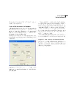
Display of results
When the required information has been entered, the
cursor will automatically be placed in the field for cal-
culation of the final result. If you are satisfied with the
entered values press
ENTER
, or if you want to make
any correction, move the field cursor to the required
field and enter the corrected values or press
DEL
to
clear averaged values.
When you move the field cursor to the field “Calc
results” and press
ENTER
, the following functions are
calculated for both the A- and C-weighted functions:
• The service equipment normalised sound pres-
sure levels L
eq, nT
, L
Smax,nT
and
LFmax,nT
•
The service equipment standardised sound pres-
sure levels L
eq, n
, L
Smax,n
and L
Fmax,n
•
The averaged corner level Lc
•
The averaged reverberant field level Lr
•
The averaged reverberation time T
•
The averaged Lc plus Lr sound pressure level L
•
The calculated reverberation index k
Use the
FUNC
key to scroll through the above mentioned
function in order to display the desired values.
If you want to go back to the menu for calculation,
press
ENTER
.
Press the
MODE
button if you want to return to nor-
mal mode of operation.
Service equipment sound pressure
levels –Engineering method
Use the
MODE
button to select the building acoustic
mode and press
8
for “Eng. Service Eq.”. Enter the val-
ue for the room volume “V” and press
ENTER
or move
the field cursor to “C” and press
ENTER
for a calcula-
tor. The calculator allows you to enter the length, width
and height of the room in order to calculate the volume.
The field cursor automatically moves between the
fields as values are entered. If you want to adjust any
previously entered value, use the arrow keys to move
the field cursor to the wanted parameter.
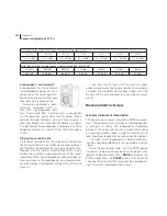
Corner position Sound Pressure Level
The first set of values to be entered is the sound pres-
sure levels Lc for the octave bands in the frequency
range 31,5 Hz to 8 kHz in the corner with the highest
C-weighted sound pressure level. The distance to the
walls and the floor should preferably be 0,5 metre,
but may due to obstacles be increased to 1,5 metre.
Press
START
for starting a measurement, or recall a
measurement by using the
RECALL
key. If measured,
the values are automatically stored.
Summary of Contents for nor140
Page 4: ......
Page 16: ......
Page 17: ...nor140 SOUND ANALYSER ...
Page 18: ......
Page 212: ...194 ...
Page 218: ......