1
2
3
4
5
6
7
8
9
10
12
11
13
*)
internal
external
+24 V
DC
0 V
DC
Installation
3-13
P/N 7146386A
E
2008 Nordson Corporation
VBN w/o Control System
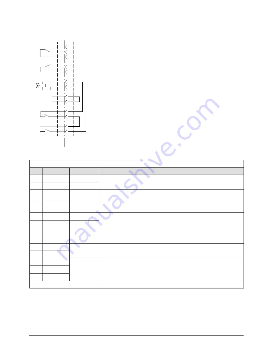
Interface Level Control
NOTE:
Available only with options
Level control
and
Level control with
overflow protection
.
NOTE:
The level control is connected to the terminal strips XLL, XS3 and
XL91. Refer to wiring diagram.
Fig. 3-14
Default bridges
Digital inputs/outputs
Pin
Input
Output
Feature
1
−
24 V
DC
Internal voltage supply of separate overflow protection
2
−
0 V
DC
3
−
24 V
DC
/ 2 A
Fill tank
- Signal to filling valve
−
Additionally with level control with overflow protection
−
*)
Tank is overfilled (contact open when level is exceeded)
4
−
5
−
−
−
Only with level control with overflow protection
−
Reset (resets signal
Tank is overfilled
)
6
−
−
7
+24 V
DC
−
Voltage supply to filling valve
8
0 V
DC
−
9
−
24 V
DC
/ 2 A Fill tank
10
−
11
−
24 V
DC
/ 2 A
−
Only with level control with overflow protection
−
Tank overfilled
NOTE:
Potential-free changeover contact for evaluation by customer
12
−
13
−
Pin 14 to 16 not assigned
Summary of Contents for VersaBlue 100H/100H
Page 46: ...Installation 3 14 P N 7146386A E 2008 Nordson Corporation VBN w o Control System...
Page 74: ...Maintenance 5 24 P N 7146386A E 2008 Nordson Corporation VBN w o Control System...
Page 94: ...Repair 7 14 P N 7146386A E 2008 Nordson Corporation VBN w o Control System...
Page 96: ...Parts 8 2 P N 7146386A E 2008 Nordson Corporation VBN w o Control System...


