95
34 - Scrub System, Disc
Adjusting Travel
If the leadscrew travel needs to be adjusted, complete
the steps below Otherwise, skip down to Setting the
Leadnut Position
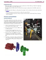
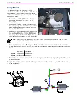
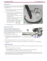
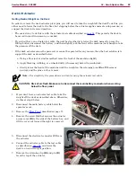
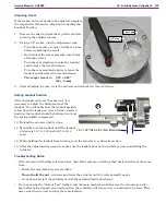
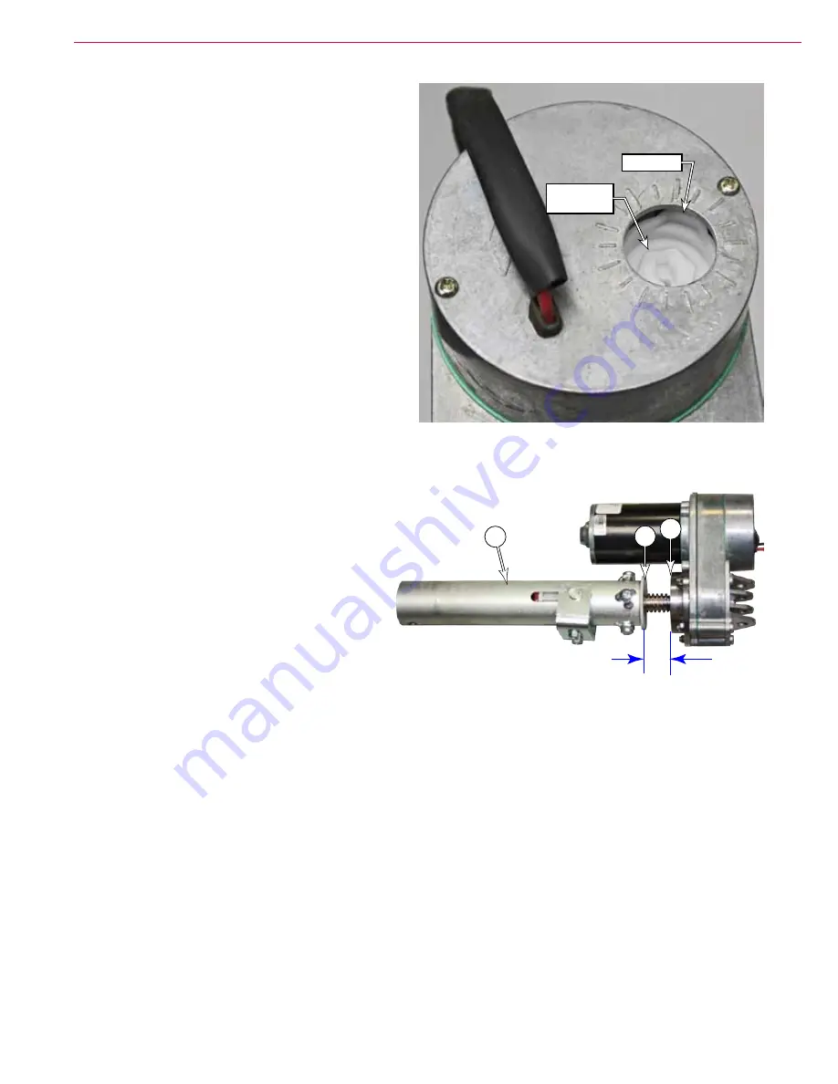
7 Remove the dust cap from the top of the actuator
covering the adjustment cam
8
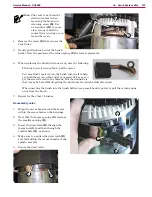
Using a 1/2” socket, turn the adjustment cam:
•
Turn the cam only a couple of clicks at a time
before rechecking the result
•
Each click of the cam represents about 2mm
of leadnut travel
•
Turn the cam clockwise to raise the leadnut
and increase the travel distance
•
Turn the cam counterclockwise to lower the
leadnut and decrease the travel distance
•
The target travel is: 2 .22 ± 0 .09”
(56 ± 2 mm)
9 After adjusting the cam, cycle the actuator and recheck the travel distance
Setting Leadnut Position
After the leadscrew travel has been set, it is
necessary to adjust the final position of the
leadnut You will notice that the leadnut position
is less than the leadscrew travel In the retracted
position, the leadnut should be bottomed out and
the spring slightly compressed
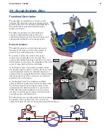
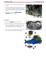
10 Extend the actuator until it stops
11 Manually turn the leadnut until the leadnut
distance is 1 67 to 1 90 inch (42 5 to 48 2
mm)
12
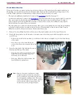
While holding the leadnut from turning, cycle the actuator to confirm its motion.
13 After the adjustment is complete, make sure the leadnut does not turn while you are reinstalling the
actuator
Troubleshooting Notes:
•
If the actuator will neither raise nor lower, then both cams are activating their limit switches at the same
time
– Rotate the cam clockwise several clicks
–
Do not hold the nut
, and raise and lower the actuator until it cycles normally again
– Go back and restart the adjustment with the extended limit adjustment
• If you are using the “Output Test” method, and the main machine controller sees the actuator go active
again after being stopped on a limit position, the controller will issue an error, and need to be reset This
may occur when you are turning the cam clockwise
Cam Lobe
1/2" Hex
Adjustment
E
G
F
1.67-1.90” (42.5-48.2 mm) Extended

