41
04 - Control System
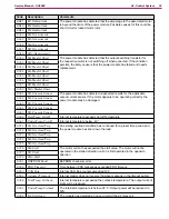
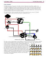
Main Control Board J1 Connector (Black)
Pin
Wire
Color
Circuit Description
Value/Condition
14
W165
GRN-BRN
H2 Back-up alarm control
32.87V off
0.014V on
15
16
W171
GRN-RED
M8 Detergent pump c
or -
12.4V off
11.5V A
0.38V B
17
W172
ORN-GRY
M8 Detergent pump c
or -
12.4V off
0.37V A
11.5V B
18
W173
BLU-YEL
M9 Detergent pump c
or -
12.4V off
11.5V A
0.38V B
19
W174
RED-WHT
M9 Detergent pump c
or -
12.4V off
0.38V A
11.5V B
20
W167
GRY
K1 KSI relay power supply
37.04V Relay energized
0.06V Relay off
21
W168
GRY
K1 KSI relay power supply
37.04V Relay energized
0.06V Relay off
22
W166
VIO-BRN
H1 Horn control
37.04V off
0.073V on
23
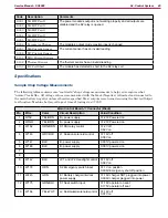
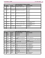
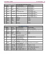
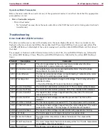
Main Control Board J2 Connector (Gray)
Pin
Wire
Color
Circuit Description
Value/Condition
1
W232
YEL
CAN 0 High
2.51V
2
W233
GRN
CAN 0 Low
2.51V
3
4
W185
BRN
B- supply for A10 smart key
reader
0.001V Powered on
5
W220
WHT
A10 Smart key reader input
3.4V Powered off or on with or without key
present
6
W148
BLK
B- power supply
0.006V Powered on
7
8
W191
WHT-ORN
S6 Recovery tank float switch
input
4.83V Float down
0.001 Float up
9
W186
BLU-BRN
S8 Side sweep proximity switch
input
4.81V Broom Down
0.001V Broom Up
10
W187
BLU
S7 Solution level sensor Lvl 1
input
4.83V Float down
0.001 Float up
11
W195
GRN
CAN 1 Low
2.446V
12
W192
YEL
CAN 1 High
2.578V
13
W188
WHT
S7 Solution level sensor Lvl 2
input
4.83V Float down
0.001 Float up

