


JAA63051-R.3689.A
- A34 ・ AF-S VR MC 105/2.8G -
⑤
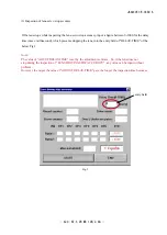
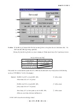
When "Fig. 1" screen is displayed, and if "OK" is clicked, "drive frequency and the motor control
adjustment" is completed. If "Adjustment could not be executed." of "Fig. 2" is displayed, make
readjustment.
Even after the readjustment, if "Fig. 2" screen is still displayed, adjust the "MR duty" again and perform
"drive frequency and the motor control adjustment" again.
However, after all the above, if the adjustment is still impossible, the SWM unit, the fixed tube unit, GMR
tape unit, or MR head unit may be defective.
Fig.1
Adjustment of Driving frequency and Motor control
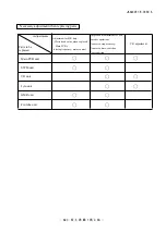
●
In case of replacing the main PCB, SWM unit and MR encoder unit, be sure to make adjustments.
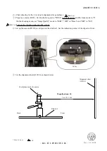
①
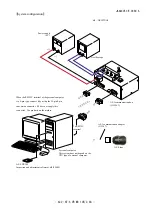
The method of connection of the rated voltage power supply and measuring tools is the same as
"ADJUSTMENT OF MR DUTY".
②
Make sure that the electric current and voltage of the rated voltage power supply are set to the set values
on the PC screen.
③
Turn the rated voltage power supply ON.
④
Select "2. ADJUSTMENT FOR DRIVING FREQUENCY & MOTOR CONTROL" in the menu of the
AF-S VR105 inspection program. The lens automatically starts the driving of scanning.
Fig.2
Summary of Contents for AF-S VR Micro Nikkor 105mm/f2.8G
Page 13: ...JAA63051 R 3689 A D11 AF S VR MC 105 2 8G Focus index unit 83 3 GMR unit Focus index unit ...
Page 100: ...JAA63051 R 3689 A A76 AF S VR MC 105 2 8G Target chart Resolution chart ...
Page 107: ...JAA63051 R 3689 A F1 AF S VR MC 105 2 8G 外観図 Sketch drawings ...
Page 108: ...JAA63051 R 3689 A F2 AF S VR MC 105 2 8G 組立図 Structure of the Lens ...
Page 109: ...JAA63051 R 3689 A F3 AF S VR MC 105 2 8G ...
Page 110: ...JAA63051 R 3689 A F4 AF S VR MC 105 2 8G ...
Page 111: ...JAA63051 R 3689 A F5 AF S VR MC 105 2 8G ...
Page 112: ...JAA63051 R 3689 A F6 AF S VR MC 105 2 8G ...
Page 113: ...JAA63051 R 3689 A F7 AF S VR MC 105 2 8G ...