JAA63051-R.3689.A
- A15 ・ AF-S VR MC 105/2.8G -
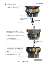
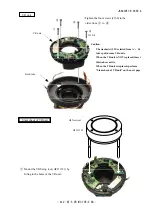
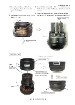
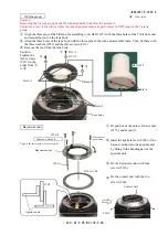
Main PCB unit
①
Connect the connector of the main PCB to the
connector of the VR unit.
②
Fix the main PCB with the three screws
(#140).
#140×3
Connector of the main PCB
Connector of the VR unit
③
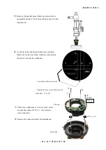
Solder the two wires and the lug plate.
④
Connect the gyro-FPC, MR-FPC, SW-FPC, focus-FPC, SWM power-FPC, and the contact unit to each
connector.
SW-FPC
Gyro-FPC
MR-FPC
Black: Lug plate
Blue: VR FPC
Black: VR FPC
Contact unit
SWM power-FPC
Arrange the two wires and attach them on
the adhesive double coated tape.
Focus-FPC
Summary of Contents for AF-S VR Micro Nikkor 105mm/f2.8G
Page 13: ...JAA63051 R 3689 A D11 AF S VR MC 105 2 8G Focus index unit 83 3 GMR unit Focus index unit ...
Page 100: ...JAA63051 R 3689 A A76 AF S VR MC 105 2 8G Target chart Resolution chart ...
Page 107: ...JAA63051 R 3689 A F1 AF S VR MC 105 2 8G 外観図 Sketch drawings ...
Page 108: ...JAA63051 R 3689 A F2 AF S VR MC 105 2 8G 組立図 Structure of the Lens ...
Page 109: ...JAA63051 R 3689 A F3 AF S VR MC 105 2 8G ...
Page 110: ...JAA63051 R 3689 A F4 AF S VR MC 105 2 8G ...
Page 111: ...JAA63051 R 3689 A F5 AF S VR MC 105 2 8G ...
Page 112: ...JAA63051 R 3689 A F6 AF S VR MC 105 2 8G ...
Page 113: ...JAA63051 R 3689 A F7 AF S VR MC 105 2 8G ...

