


CHAPTER 11 PWM UNIT
User’s Manual U11969EJ3V0UM00
333
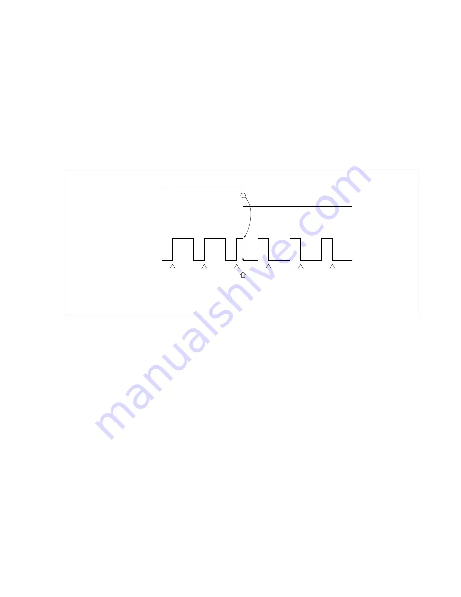
11.4.3 Specification of active level of PWM pulse
The PALVn bit of the PWM control register (PWMCn) specifies the active level of the PWM pulse output from the
PWM output pin (n = 0 to 3).
When the PALVn bit is set (1), a pulse with high active level is output, and when it is cleared (0), a pulse with low
active level is output.
When the PALVn bit is rewritten, the active level of the PWM output immediately changes. Figure 11-6 shows
the active level setting and the pin status of the PWM output.
The active level of the PWM output can be changed by manipulating the PALVn bit, regardless of the setting of
the PWMEn bit (enabling/disabling PWM).
Figure 11-6. Setting of Active Level of PWM Output
Remark
PWMEn = 1 (n = 0 to 3)
11.4.4 Specification of PWM pulse width rewrite cycle
Starting PWM output and changing the PWM pulse width are performed in synchronization either with each 2
(x+8)
cycles (2
(x+8)
/f
PWMC
) of the PWM pulse or with each 1 cycle (2
x
/f
PWMC
) of the PWM pulse. The specification of the PWM
pulse width rewrite cycle is performed with the SYNn bit of the PWMCn register (n = 0 to 3).
When the SYNn bit is cleared (0), the pulse width is changed at every 2
(x+8)
cycles (2
(x+8)
/f
PWMC
) of the PWM pulse.
Therefore, it will take 2
(x+8)
clocks max. before the pulse with the width corresponding to the data written to the PWMn
register is output.
Figure 11-7 shows an example of the PWM output timing.
On the other hand, when the SYNn bit is set (1), the pulse width is changed at every 1 cycle of the PWM pulse
(2
x
/f
PWMC
). In this case, it will take 2
x
clocks max. before the pulse with the width corresponding to the data written
to the PWMn register is output.
When the PWM pulse rewriting cycle is specified as every 2
x
/f
PWMC
(when the SYNn bit is set (1)), the accuracy
of the PWM pulse gained is x bits or more and (x+8) bits or less, which is lower than the accuracy when the rewriting
cycle is specified as 2
(x+8)
/f
PWMC
. However, the response is improved because the repeat frequency is increased.
Figure 11-8 shows an example of the PWM output timing when the rewrite timing is 2
x
/f
PWMC
.
PALVn
(High active)
(Low active)
PWMn
(Rewriting PALVn bit)
Summary of Contents for V854 UPD703006
Page 2: ...2 User s Manual U11969EJ3V0UM00 MEMO ...
Page 22: ...22 User s Manual U11969EJ3V0UM00 MEMO ...
Page 80: ...80 User s Manual U11969EJ3V0UM00 MEMO ...
Page 134: ...134 User s Manual U11969EJ3V0UM00 MEMO ...
Page 156: ...156 User s Manual U11969EJ3V0UM00 MEMO ...
Page 294: ...294 User s Manual U11969EJ3V0UM00 MEMO ...
Page 320: ...320 User s Manual U11969EJ3V0UM00 MEMO ...
Page 324: ...324 User s Manual U11969EJ3V0UM00 MEMO ...
Page 336: ...336 User s Manual U11969EJ3V0UM00 MEMO ...
Page 376: ...376 User s Manual U11969EJ3V0UM00 MEMO ...
Page 382: ...382 User s Manual U11969EJ3V0UM00 MEMO ...
Page 394: ...394 User s Manual U11969EJ3V0UM00 MEMO ...


