


User’s Manual U11969EJ3V0UM00
193
CHAPTER 7 TIMER/COUNTER FUNCTION (REAL-TIME PULSE UNIT)
7.7.4 Clearing/starting timer
There are three methods of clearing/starting timer 3: by coincidence of compare register, by capture trigger of CC3,
and by software.
(1) Clearing/starting by compare coincidence of CC3
If CC3 is specified as a compare register by the CMS 3 bit, TM3 clears its value at the next count clock and
starts count operation when the set value of the compare register (CC3) and the value of TM3 coincide. At
the same time, an interrupt request (INTCC30) is generated.
The interval timer set to a compare register can be calculated by the following expression:
(Set value + 1) x Count cycle
For the details, refer to 7.7.6 Compare operation.
(2) Clearing/staring by capture trigger of CC3
If CC3 is specified as a capture register by the CMS3 bit, when a capture trigger of CC3 is generated, the
count value of TM3 is captured in CC3, TM3 is cleared, and count operation is started. At the same time,
an interrupt request (INTCC3) is generated.
(3) Clearing/starting by software
When the CS3 bit of the TMC3 register is set to 1, the TM1 register clears its value and start counting from
0.
However, this setting of the bit is valid only when the value of the CE3 bit is 1.
7.7.5 Capture operation
When the TMC3 register is set as a capture register, the capture/compare register (CC3) performs a capture
operation that captures and holds the count value of TM3 and loads it to a capture register in synchronization with
an external trigger and in asynchronization with the count clock. The valid edge from the external interrupt request
input pin INTP30 is used as the capture trigger. In synchronization with this capture trigger signal the count values
of TM3 during counting are captured and loaded to the capture register. The value of the capture register is retained
until the next capture trigger is generated.
When the capture timing of the capture register and the write operation to the register are in contention, the latter
is given priority and the capture operation is ignored.
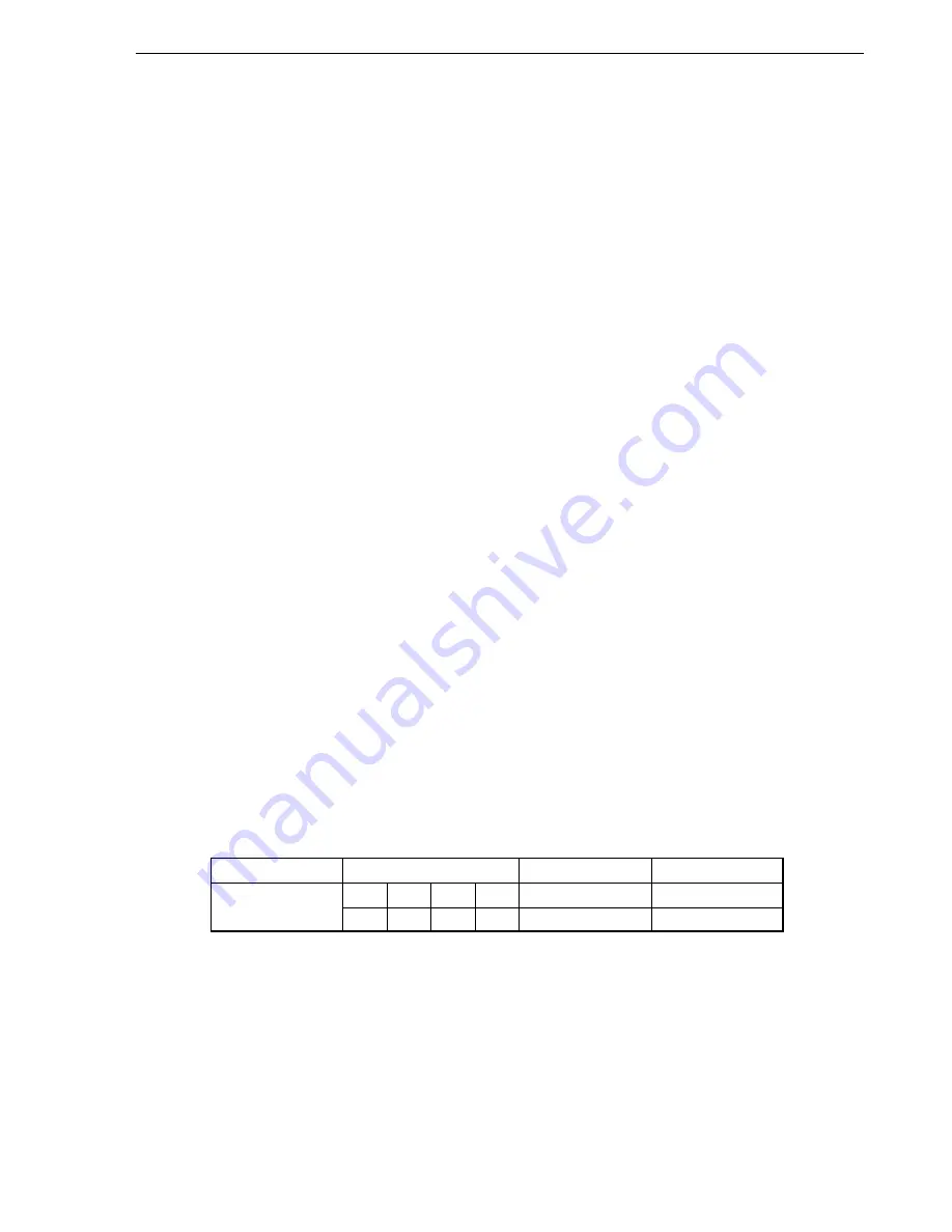
Table 7-6. Capture Trigger Signal to 16-Bit Capture Register
Capture Source
Selection of Valid Edge
Capture Trigger
Interrupt Request
INTP30
↓
↑
—
↑↓
CC3
INTCC3
↑
↓
↑↓
—
CP3
—
The valid edge of the capture trigger is set by the external interrupt mode register (INTM7). When the CC3 trigger
is set to the falling edge and the CP3 trigger is set to the rising edge, input pulse width and input pulse cycle from
external can be measured with one interrupt (INTCC3).
Summary of Contents for V854 UPD703006
Page 2: ...2 User s Manual U11969EJ3V0UM00 MEMO ...
Page 22: ...22 User s Manual U11969EJ3V0UM00 MEMO ...
Page 80: ...80 User s Manual U11969EJ3V0UM00 MEMO ...
Page 134: ...134 User s Manual U11969EJ3V0UM00 MEMO ...
Page 156: ...156 User s Manual U11969EJ3V0UM00 MEMO ...
Page 294: ...294 User s Manual U11969EJ3V0UM00 MEMO ...
Page 320: ...320 User s Manual U11969EJ3V0UM00 MEMO ...
Page 324: ...324 User s Manual U11969EJ3V0UM00 MEMO ...
Page 336: ...336 User s Manual U11969EJ3V0UM00 MEMO ...
Page 376: ...376 User s Manual U11969EJ3V0UM00 MEMO ...
Page 382: ...382 User s Manual U11969EJ3V0UM00 MEMO ...
Page 394: ...394 User s Manual U11969EJ3V0UM00 MEMO ...


