Configuring Your Server 4-49
The following describe the clearing procedure.
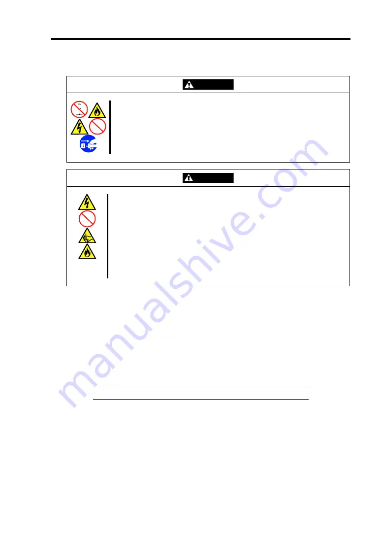
WARNING
Observe the following instructions to use the server safely. Failure to follow
these instructions may result in death or serious personal injury. See pages 1-3
to 1-8 for details.
■
Do not disassemble, repair, or alter the server.
■
Do not remove the lithium battery.
■
Do not connect the ground line to a gas pipe.
CAUTION
Observe the following instructions to use the server safely. Failure to follow
these instructions may result in death or serious personal injury. See pages 1-3
to 1-8 for details.
■
Never attempt to lift the server with two or less persons.
■
Make sure to complete board installation.
■
Do not install the server on a rack with leaving covers removed.
■
Do not pinch your finger with mechanical components.
■
Note high temperature.
■
Do not pull out a device from the rack if the rack is unstable.
■
Do not leave more than one device being pulled out from the rack.
Clearing CMOS Data
1.
See the section "Preparing for Installation and Removal" as described in Chapter 9 of this
guide to prepare.
2.
Remove the side cover.
3.
Locate the position of the jumpers on the mother board you are changing.
4.
Move the jumper strap to the CMOS clear position.
Refer to the previous illustration to find the location of the jumper.
IMPORTANT:
Keep the removed jumper strap for future use.
5.
Wait for a while (about 5 seconds), and then reinstall the jumper block to the default
position.
6.
Reinstall the side cover removed in Step 2.
7.
Plug the power cord to your server and turn on the server.
8.
Press
F2
at the prompt to run the BIOS SETUP utility, and select "Load Setup Defaults"
at the Exit menu.
Summary of Contents for Express5800 120Li
Page 16: ...x This page is intentionally left blank ...
Page 54: ...2 26 General Description This page is intentionally left blank ...
Page 180: ...7 12 Maintenance This page is intentionally left blank ...
Page 214: ...8 34 Troubleshooting This page is intentionally left blank ...
Page 277: ...Chapter 10 Internal Cabling Diagrams Internal cable connections of the server are shown below ...
Page 286: ...10 10 Internal Cabling Diagrams This page is intentionally left blank ...
Page 344: ...F 4 Product Configuration Record Table This page is intentionally left blank ...


