95
14.
PROGRAMMED MAINTENANCE REGISTER - PROGRAMMIERTES
WARTUNGSREGISTER
Regulation (EC) No 2037/2000 of the European Parliament and of the Council of 29 June 2000 on Sub-
stances that Deplete the Ozone Layer
The System manager must keep a system booklet in accordance with the regulation.
The following operations must be recorded in the system booklet. The operations of recovery and recycling of the
controlled substances contained in the frigorific circuit must be carried out with devices in accordance to the char-
acteristics and in the respect of the technical norms established from norm ISO 11650.
Characteristics of the systems to be checked.
Systems and equipments with a refrigerating fluid charge of more than 3 kg shall be checked for leakages annually
(every 6 months if more than 30 kg) and the result shall be recordered in the system booklet (Regulation EC No
842/2006). When an indication of leakage is identified during an inspection, a research with a leak detector shall be
done. The leak detector shall have the sensibility bigger than 5 g/year.The research on the high pressure side must
be made with the system turned on, while the one on the low pressure side must be made with the system turned
off. In case of leakage that needs a recharge bigger than the 10% of the total charge of the circuit refrigerator, the
system or the equipment must be repaired within thirty days. The system can work again only after this operation.
The results of these checks shall be recorded in the system booklet.
Verordnung (EG) Nr. 2037/2000 des Europ
a
ischen Parlaments und des Rates vom 29. Juni 2000
u
ber
Stoffe, die zum Abbau der Ozonschicht f
u
hren
Der Systemmanager muss ein Systemheft in
U
bereinstimmung mit der Verordnung.
Die folgenden T
a
tigkeiten m
u
ssen in das Systemheft eingetragen werden. R
u
ckgewinnung und Recycling der im
K
u
hlkreislauf enthaltenen Gefahrenstoffe m
u
ssen mit Hilfe von Vorrichtungen gem
aö
den Eigenschaften und unter
Einhaltung der technischen Normen, wie sie in der ISO-Norm 11650 festgelegt sind, erfolgen.
Eigenschaften des zu
u
berpr
u
fenden Systems.
Systeme und Ausstattungen, die mehr als 3 kg K
u
hlfl
u
ssigkeit enthalten, m
u
ssen j
a
hrlich auf undichte Stellen hin
untersucht werden (halbj
a
hrlich wenn mehr als 30 kg). Die Ergebnisse dieser
U
berpr
u
fung m
u
ssen in das System-
heft eingetragen werden (Verordnung EG Nr 842/2006).
Wird w
a
hrend der
U
berpr
u
fung eine undichte Stelle ausfindig gemacht, so muss eine Untersuchung mit Hilfe eines
Lecksuchger
a
ts vorgenommen werden. Das Lecksuchger
a
t muss eine Pr
u
fempflindlichkeit von mehr als 5 g pro
Jahr aufweisen.
Die Untersuchung auf der Hochdruckseite hat bei eingeschaltetem System zu erfolgen, w
a
hrend die Untersuchung
auf der Niederdruckseite bei ausgeschaltetem System zu erfolgen hat.
Im Falle von Lecks, bei denen ein Nachf
u
llen in H
o
he von mehr als 10 % der Gesamtmenge der K
u
hlfl
u
ssigkeit im
K
u
hlkreislauf erforderlich ist, muss das System beziehungsweise die Ausstattung innerhalb von drei
ö
ig Tagen repa-
riert werden. Das System kann erst nach Durchf
u
hrung dieser T
a
tigkeit wieder arbeiten. Die Ergebnisse dieser
U
berpr
u
fungen m
u
ssen in das Systemheft eingetragen werden.
Summary of Contents for OCGE 111
Page 69: ...69 11 2 WIRING DIAGRAM MODELS PCGE 11 to PCGE 25 PCGEZ 08 230V 1Ph 50Hz POWER COMMAND DIAGRAM ...
Page 70: ...70 MODEL PCGE 28 230V 1Ph 50Hz POWER COMMAND DIAGRAM ...
Page 71: ...71 MODEL PCGE 28 400V 3Ph 50Hz POWER COMMAND DIAGRAM ...
Page 72: ...72 MODELS PCGE 31 to PCGE 41 OCGE 31 to OCGE 41 230V 1Ph 50Hz POWER SECTION ...
Page 73: ...73 MODELS PCGE 31 to PCGE 41 OCGE 31 to OCGE 41 230V 1Ph 50Hz COMMAND SECTION ...
Page 78: ...78 MODELS PCGE 590 to PCGE 3300 PCGEZ 360 to PCGEZ 480 400V 3Ph 50Hz ...
Page 79: ...79 ...
Page 80: ...80 ...
Page 81: ...81 ...
Page 86: ...86 MODEL PCGE 1100 with tank and pump MODEL PCGE 1300 with tank and pump ...
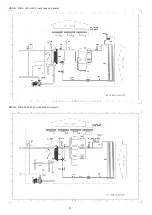
Page 87: ...87 MODEL PCGE 1900 2200 with tank and pump MODEL PCGE 2900 3300 with tank and pump ...
Page 91: ...91 MODEL PCGE 1100 without tank MODEL PCGE 1300 without tank ...
Page 92: ...92 MODEL PCGE 1900 2200 without tank MODEL PCGE 2900 3300 without tank ...
Page 97: ...97 710 1789 00 00 02B 轜 07 05 2008 ...
Page 166: ...69 11 2 WIRING DIAGRAM MODELS PCGE 11 to PCGE 25 PCGEZ 08 230V 1Ph 50Hz POWER COMMAND DIAGRAM ...
Page 167: ...70 MODEL PCGE 28 230V 1Ph 50Hz POWER COMMAND DIAGRAM ...
Page 168: ...71 MODEL PCGE 28 400V 3Ph 50Hz POWER COMMAND DIAGRAM ...
Page 169: ...72 MODELS PCGE 31 to PCGE 41 OCGE 31 to OCGE 41 230V 1Ph 50Hz POWER SECTION ...
Page 170: ...73 MODELS PCGE 31 to PCGE 41 OCGE 31 to OCGE 41 230V 1Ph 50Hz COMMAND SECTION ...
Page 175: ...78 MODELS PCGE 590 to PCGE 3300 PCGEZ 360 to PCGEZ 480 400V 3Ph 50Hz ...
Page 176: ...79 ...
Page 177: ...80 ...
Page 178: ...81 ...
Page 183: ...86 MODEL PCGE 1100 with tank and pump MODEL PCGE 1300 with tank and pump ...
Page 184: ...87 MODEL PCGE 1900 2200 with tank and pump MODEL PCGE 2900 3300 with tank and pump ...
Page 188: ...91 MODEL PCGE 1100 without tank MODEL PCGE 1300 without tank ...
Page 189: ...92 MODEL PCGE 1900 2200 without tank MODEL PCGE 2900 3300 without tank ...


