


21
These delay times are preset for the compressor:
Delay type
Description
Controller
Type
”
A
’
Controller
Type
”
B
’
Controller
Type
”
C
’
Delay at start-up (power ON)
Set a time delay at compressor start-up to graduate the
starting current of the chiller and so that the compres-
sor is protected against repeated start-ups when there
is an interruption in the power supply.
/
~300
~300
Minimum operating time
Sets the time that the compressor has to remain in op-
eration after it has been switched on, even if there is no
further request for this.
/
~60
~60
Minimum switching-off time
Sets the time that the compressor has to remain out of
operation after it has been switched off, even if there is
a request to switch it on. During this phase the LED for
the compressor flashes.
/
~60
~60
Time interval between two con-
secutive ON routines
This sets the minimum switch-off interval between two
consecutive ON routines for the compressor (the maxi-
mum number of ON routines per hour is displayed).
During this phase the LED for the compressor flashes.
~360
/
/
Delay in switching on the com-
pressor after switching on the
pump
This sets the time between switching on the pump and
switching on the compressor.
/
~10
~10
Please follow the instructions given below for starting up and operating the chiller.
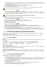
6.4.1
CONTROLLER TYPE
”
A
Ü
(PCGE 11 TO PCGE 28; PCGEZ 08)
The operating thermostat is supplied in a pre-adjusted state according to the standard specifications of the chiller
listed in the supplement. The operating thermostat controls both the temperature adaptation functions and the
other safety parameters (e.g. alarm management and the running time of the electric motors). The complete list of
parameters in not supplied to the customer because changes in certain parameters may lead to problems affecting
the reliability and characteristics of the chiller.
Instructions for changing the parameters required by the user:
Proceed as follows to change the SET-POINT value:
1.
Press the
key for 2 seconds (the LED starts to flash).
2.
Use the
and
arrows to change the SETPOINT.
3.
Press
or wait 15 sec. (timeout), without pressing any key.
To access the
”
Pr1
’
user level:
1.
Press the
+
keys for a few seconds (the and LEDs start to flash), the display shows the initial pa-
rameters.
2.
Use the
and
arrows to change the parameter.
3.
Press the
key to change its value.
4.
Change the value with the
and
keys.
5.
Press the
key again to confirm the new value. After a few seconds, the next parameter appears.
To exit programming:
Press the
+
keys when a parameter is displayed or wait 15 sec. (timeout), without pressing any key.
NOTE:
The new parameter value is also saved if no
keys are pressed during the timeout.
Press the
key while programming in order to scroll through the parameter codes or increase the value.
The following parameters can be changed by means of the procedure described above:
Standard value
Code
Meaning
PCGE
with tank
PCGE*
without
tank
PCGEZ
with
tank
PCGEZ*
without
tank
Set
Set-point
15
20
-10
-5
Hy
Differential
3
3
3
3
Please contact the manufacturer for other parameters. (*probe set-point at inlet)
Summary of Contents for OCGE 111
Page 69: ...69 11 2 WIRING DIAGRAM MODELS PCGE 11 to PCGE 25 PCGEZ 08 230V 1Ph 50Hz POWER COMMAND DIAGRAM ...
Page 70: ...70 MODEL PCGE 28 230V 1Ph 50Hz POWER COMMAND DIAGRAM ...
Page 71: ...71 MODEL PCGE 28 400V 3Ph 50Hz POWER COMMAND DIAGRAM ...
Page 72: ...72 MODELS PCGE 31 to PCGE 41 OCGE 31 to OCGE 41 230V 1Ph 50Hz POWER SECTION ...
Page 73: ...73 MODELS PCGE 31 to PCGE 41 OCGE 31 to OCGE 41 230V 1Ph 50Hz COMMAND SECTION ...
Page 78: ...78 MODELS PCGE 590 to PCGE 3300 PCGEZ 360 to PCGEZ 480 400V 3Ph 50Hz ...
Page 79: ...79 ...
Page 80: ...80 ...
Page 81: ...81 ...
Page 86: ...86 MODEL PCGE 1100 with tank and pump MODEL PCGE 1300 with tank and pump ...
Page 87: ...87 MODEL PCGE 1900 2200 with tank and pump MODEL PCGE 2900 3300 with tank and pump ...
Page 91: ...91 MODEL PCGE 1100 without tank MODEL PCGE 1300 without tank ...
Page 92: ...92 MODEL PCGE 1900 2200 without tank MODEL PCGE 2900 3300 without tank ...
Page 97: ...97 710 1789 00 00 02B 轜 07 05 2008 ...
Page 166: ...69 11 2 WIRING DIAGRAM MODELS PCGE 11 to PCGE 25 PCGEZ 08 230V 1Ph 50Hz POWER COMMAND DIAGRAM ...
Page 167: ...70 MODEL PCGE 28 230V 1Ph 50Hz POWER COMMAND DIAGRAM ...
Page 168: ...71 MODEL PCGE 28 400V 3Ph 50Hz POWER COMMAND DIAGRAM ...
Page 169: ...72 MODELS PCGE 31 to PCGE 41 OCGE 31 to OCGE 41 230V 1Ph 50Hz POWER SECTION ...
Page 170: ...73 MODELS PCGE 31 to PCGE 41 OCGE 31 to OCGE 41 230V 1Ph 50Hz COMMAND SECTION ...
Page 175: ...78 MODELS PCGE 590 to PCGE 3300 PCGEZ 360 to PCGEZ 480 400V 3Ph 50Hz ...
Page 176: ...79 ...
Page 177: ...80 ...
Page 178: ...81 ...
Page 183: ...86 MODEL PCGE 1100 with tank and pump MODEL PCGE 1300 with tank and pump ...
Page 184: ...87 MODEL PCGE 1900 2200 with tank and pump MODEL PCGE 2900 3300 with tank and pump ...
Page 188: ...91 MODEL PCGE 1100 without tank MODEL PCGE 1300 without tank ...
Page 189: ...92 MODEL PCGE 1900 2200 without tank MODEL PCGE 2900 3300 without tank ...