background image

User’s Guide

Spitfire 100 Extreme

For Maintenance Kits, Spares,

Service and Support

Call: +44 (0) 1628 588755

E-mail:

[email protected]

Summary of Contents for Spitfire 100 Extreme

Page 1: ...User s Guide Spitfire 100 Extreme For Maintenance Kits Spares Service and Support Call 44 0 1628 588755 E mail support colourgen com ...

Page 2: ...Spitfire 100 Extreme series printers User s Guide 2 AP 75194 Rev 2 2 ...

Page 3: ...es printers In consideration of the furnishing of the information contained in this document the party to whom it is given assumes its custody and control and agrees to the following The information herein contained is given in confidence and any part thereof shall not be copied or reproduced without written consent of Mutoh Belgium nv This document or the contents herein under no circumstances sh...

Page 4: ...Spitfire 100 Extreme series printers User s Guide 4 AP 75194 Rev 2 2 ...

Page 5: ...he winding system 31 3 4 Media handling 32 3 5 Ink cassettes 41 3 6 Replacing the cutting blade 43 3 7 Replacing the waste bottle 44 3 8 Working with Mutoh s SmartChip management System 45 3 9 Switch between ink configurations 49 3 10 Unattended printing or leave printer idle during night 50 3 11 LongStore 52 3 12 Transferring the printer 56 4 Periodical maintenance 59 4 1 P er i odi c a l S er v ...

Page 6: ...sed Mutoh technician 74 5 Prepartions before printing 75 5 1 Using media 76 5 2 Testprinting 79 5 3 Set the correct distance adjust step 85 5 4 Printing flow 89 6 Printer menu 91 6 1 How to work in the menu 95 6 2 Operation panel IN standby mode 97 6 3 Operating panel during printing 102 6 4 Operations after printing 106 6 5 Menu overview 1 7 7 7 108 7 Troubleshooting 165 7 1 Introduction 166 7 2 ...

Page 7: ...S waste 9 1 4 Warnings Cautions and Notes 10 1 5 SAFETY INSTRUCTIONS 10 1 6 Warning labels 12 1 6 1 Handling the warning labels 12 1 6 2 Position of the warning labels 12 1 6 2 1 Front of the machine 12 1 6 2 2 Rear of the machine 13 1 6 2 3 Types of warning labels on the winding system 14 1 6 3 Labels in function of transportation 15 1 6 4 Ink related labels 16 ...

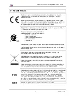
Page 8: ... is designed and manufactured with high quality materials and components which can be recycled and reused When this crossed out wheeled bin symbol is attached to a product it means the product is covered by the European Directive 2002 96 EC WEEE regulation Please inform yourself about the local separate collection system for electrical and electronic products Please act according to local rules an...

Page 9: ... information carefully All safety data sheets are periodically updated These sheets and their translations can be found on www mutoh eu Products Downloads extra msds Only use original manufacturer s ink and appropriate cleaning liquid Before installing an ink holder shake it gently Doing so will preserve print quality When ink is moved from a cold place to a warm place keep the ink for three hours...

Page 10: ...heavy objects on the cable Do not bend twist knot or pull the cable Do not wire the cable near equipment that generates heat Do not use the cable with any other electrical device Do not handle the cable with wet hands Be aware of all caution and warning labels to avoid potentially hazardous situations To prevent fire or electrical shock machines must be connected to a properly grounded electrical ...

Page 11: ...hine Do not use thinner benzene alcohol or other active agents Doing so may result in damage or paint peeling from the casing Do not bend or pull the waste fluid tube Doing so may cause waste fluid to leak out and malfunction of the product Do not tilt the machine place it against a wall or turn it upside down Doing so may cause ink to leak inside the machine Movement after transport is also not c...

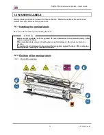
Page 12: ...o note the following when handling the labels Notes Make sure that all labels can be recognized If text or illustrations cannot be seen clearly either clean or replace the label When cleaning labels use a cloth with water or neutral detergent Do not use a solvent or gasoline If a warning label is damaged lost or cannot be recognized replace the label When replacing warning labels contact your loca...

Page 13: ...Spitfire 100 Extreme series printers User s Guide 13 AP 75194 Rev 2 2 1 6 2 2 Rear of the machine ...

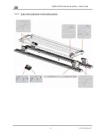
Page 14: ...Spitfire 100 Extreme series printers User s Guide 14 AP 75194 Rev 2 2 1 6 2 3 Types of warning labels on the winding system ...

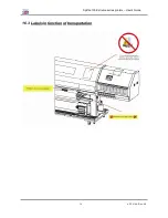
Page 15: ...Spitfire 100 Extreme series printers User s Guide 15 AP 75194 Rev 2 2 1 6 3 Labels in function of transportation ...

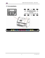
Page 16: ... Extreme series printers User s Guide 16 AP 75194 Rev 2 2 1 6 4 Ink related labels 1 2 P1 P2 P3 3 4 P4 5 P5 6 P6 7 P7 8 P8 9 10 11 12 13 14 15 16 HEAD 1 HEAD 2 HEAD 3 HEAD 4 HEAD 5 HEAD 6 HEAD 7 HEAD 8 4x4 colours ...

Page 17: ...94 Rev 2 2 2 PRODUCT OVERVIEW 2 1 Part names and functions 18 2 1 1 Front 18 2 1 2 Rear 19 2 1 3 Heater system 20 2 1 4 Operation panel 21 2 1 4 1 Printer 21 2 1 4 2 Winding System 23 2 2 Installation requirements 24 2 2 1 Environment 24 2 2 2 Working space 25 ...

Page 18: ...d white 5 Operation panel This panel is used to set operational conditions the status of the printer and other functions 6 SmartChip Management System To control the ink volume on your printer 7 Ink compartment Sixteen slots available to install ink cassettes 8 LED indicators Indicates if there is a cassette in the slot below the LED and if it is empty or not 9 Waste bottle To collect the waste fl...

Page 19: ...the power plug is connected 3 BIS CLIB To connect the optional Bulk Ink System 4 BIS Sensors To connect the sensor cable of the optional Bulk Ink System with the printer 5 Insertion slot Network card installed To connect the network cable 6 Hard disk slot For the hard disk 7 Waste bottle connector To connect the waste bottle sensor cable 8 Foot switch connectors To connect the footswitches to lowe...

Page 20: ...process and helps to make the prints touch dry Dryer Heater D 20 50 C The dryer completes the drying for compatibility with the take up in combination with higher output speeds There have been a number of requests from the field asking the heaters to be on by default for a few user settings This has now been implemented as follows For user 1 and user 8 default settings are as follows a Pre heater ...

Page 21: ...ON and OFF 2 Executes the function assigned to F1 Executes the function assigned to F1 3 Executes the function assigned to F2 Executes the function assigned to F2 4 Executes the function assigned to F3 Executes the function assigned to F3 5 Executes the function assigned to F4 Executes the function assigned to F4 6 Changes the LCD monitor display to the setup menu status Changes the menu in revers...

Page 22: ... The printer is waiting to receive print data 14 Orange ON The pressure roller is in the release position Media has not been loaded OFF The pressure roller is in the secured position The media has not been loaded 15 Orange ON The temperature of the heating elements is at the requested temperature The real temperature is the same as the requested temperature Flashing The heating elements are warmin...

Page 23: ...0 LED Manual LED lights up when pushing one of the buttons Motor turns LED flashes Motor is off LED is out Motor accelerates LED burns continuously Automatic Outside printing Inside printing 4 Backwards button Roll off unwinder Roll up unwinder 5 Forwards button Roll up unwinder Roll off unwinder 6 Winder 100 switch Toggle between Manual 0 and Automatic I mode 7 Winder 100 LED Manual LED lights up...

Page 24: ... building installation should be equipped with an automatic breaker double pole of 20 A and an earth leakage switch of 300 mA Environmental Recommended working environment Temperature 23 C Humidity 55 without condensation Operational conditions Temperature 20 C 30 C Humidity 40 to 65 without condensation Rate of change Temperature No more than 2 C per hour Humidity No more than 5 per hour Storage ...

Page 25: ... 2 2 Working space Install the product on a flat surface that fulfils following conditions Recommended space A 1 meter B 2 meter C 2 5 meter D 2 meter E 3 meter Notes These are recommended values When loading media with a trolley or manually different values should be used ...

Page 26: ...Spitfire 100 Extreme series printers User s Guide 26 AP 75194 Rev 2 2 ...

Page 27: ...eplacing the cutting blade 43 3 6 1 Replacement time 43 3 6 2 Replacement procedure 43 3 7 Replacing the waste bottle 44 3 7 1 Replacement Time 44 3 7 2 Replacement Procedures 44 3 8 Working with Mutoh s SmartChip management System 45 3 8 1 Introduction 45 3 8 2 Selecting the correct modes 46 3 8 3 Transferring ink volume 47 3 8 3 1 Via the smart chip reader slot 47 3 8 3 2 Via the Cassette slots ...

Page 28: ...ire 100 Extreme series printers User s Guide 28 AP 75194 Rev 2 2 3 11 2 Starting up after a LongStore 54 3 12 Transferring the printer 56 3 12 1 Hints tips and warnings 56 3 12 2 Transferring the printer 57 ...

Page 29: ...e printer will ask if you want to clean the wipers When it is the first start up in a few hours it is highly recommended to press YES F2 and to clean the wipers with Mutoh Mild cleaning in order to remove all ink and to make the wipers more elastic Step 3 Press the ENTER key when you have done The carriage will cap in again Step 4 After finishing the daily maintenance the print will automatically ...

Page 30: ...a nozzle check to ensure all nozzles are present If not perform the necessary cleaning cycles 3 2 POWERING OFF Notes Please be sure to perform the necessary maintenance before powering OFF the machine All details can be found in chapter 4 Step 1 Verify the following regarding the operational condition of the printer There is no printing operation being performed The operation panel is in the main ...

Page 31: ... ON OFF THE WINDING SYSTEM There is a switch located on the power supply box of the winding system Its status is marked with O and I I Switched ON Power LED on control panel of winding system will light up O Switched OFF Power LED on control panel of winding system will not be lid ...

Page 32: ...e find below the different profiles and decide which one to use OFF Roll LeftRight Roll LeftRightTop Roll to Roll Sheet Measurement None Left Right Left Right Top Left Right Left Right Top Bottom Take Up Not used Not used Not used Used Not used SlantCheck No Yes Yes Yes No Cutting media possible Yes Yes Yes Yes no auto cut Yes Cut Test No No Yes No Yes Feeder speed Low Low Low Low High Load the me...

Page 33: ...les Step 4 Make sure both unwinder REAR and winder FRONT unit are set to MANUAL mode Step 5 Consider the specifications of the printer before loading media Metrical Imperial Maximum loading capacity 100 kg 220 lb Maximum width 2604 mm 102 5 in Inner core diameter 50 8 mm or 76 2 mm 2 in or 3 in Step 6 Remove the packaging of the media roll Step 7 Check whether the media is inside or outside printa...

Page 34: ... easily checked by the yellow labels on the winding rails Be sure to mount the left and right roll unit on the same distance from the 0I0 label Step 11 Install an empty core between the front roll units A Make sure the core is longer than the media width B Load it centrally as described in previous step C Install a media core brace in case the media is wider than 2 meter This to prevent the media ...

Page 35: ...t platform and pressure rollers Step 14 Take the media on the front of the printer and pull until the rear tensioning system gently hits the back of the machine This to become an equal tension Step 15 Lower the pressure rollers by pressing the F4 key or using the foot pedal Step 16 Set the unwinder REAR unit to AUTOMATIC The rear tensioning system will go to its initial position Notes Be sure to m...

Page 36: ... dots on the print platform Set width in Utility menu Use Roll LeftRight for flexible media and Roll LeftRightTop for rigid media In the second option a media cut test will be performed which means scrolling back and forward of the media backwards feeding When loading flexible media it could get stuck into the media groove and can cause head strikes Go to step 20 when you have chosen for OFF Roll ...

Page 37: ...ofiles for media measurement F4 key Start media measurement using the selected profile in the lower left corner Step 21 Set the winder FRONT unit to ACTIVE The front tensioning system will be activated Step 22 Install the media retainers if necessary as explained in one of the next chapters Step 23 Installation of the media is completed Notes With a small intervention it is possible to reverse you...

Page 38: ...d straight to avoid slant errors Step 7 Lower the pressure rollers by pressing the F4 key or using the foot pedal Step 8 Decide which kind of media measurement should be done The following profiles are available Profiles Settings OFF Sheet Measurement None Left Right Top Bottom Take Up Not used Not used SlantCheck No No Cutting media possible Yes Yes Cut Test No Yes Feeder speed Low High Align med...

Page 39: ...ert them from the left side of the machine Be sure the pins are correctly installed in the grooves Step 2 Move the right media retainer to the far right side and the left media retainer to the most left side Step 3 Install the roll media as explained in previous chapters Step 4 After the initializing of the paper shove the media retainers over the media edges Caution Do not push the media retainer...

Page 40: ...eady 3 spacers installed per brace with an outer diameter of 74 mm In box 3 4 there are 6 spacers of 76 mm Please follow the instructions below to install and use the braces correctly Step 1 First check which spacer fits the best in the used core If this one is not installed yet remove the installed one with a Hexagon Wrench 2 mm in box 2 4 and install the correct one as shown below There is alrea...

Page 41: ...ng two ink related messages can be displayed Ink Near End message This message will be displayed when there is only 6 of ink left in the ink cassette The numbers correspond the near empty ink cassettes You can print until the Ink End message is displayed Be sure to have a new cassette at hand Ink End message This message will be displayed when the flag 2 in the cassette comes out The cassette has ...

Page 42: ... the latest price list to know the available ink and cleaning cassettes for the Spitfire 100 Extreme and for the latest price and part numbers 3 5 3 Replacement procedure Step 1 Remove the empty ink cassette s when shown on the display or when the empty lamp on the LED bar is lit Step 2 Dispose the used ink cassette by putting it in a plastic bag in accordance with local regulations or laws Step 3...

Page 43: ...e normal status The MEDIA SET light goes off Step 2 Go to the H Unlock menu SetupMenu 5 7 and unlock the head Step 3 Open the front cover Step 4 While pressing the cutting blade holder tab rotate the cutting blade holder lever in the direction shown on the picture 2 Step 5 Take out the cutting blade 3 and insert the new cutter into the media cutting blade holder 4 Step 6 While slightly pressing th...

Page 44: ...light is off Step 2 Lower the waste ink tank tray till it touches the sensor at the bottom Step 3 Remove the waste ink bottle Step 4 Replace the full one with an empty one in the box and empty the full one Notes Put the used waste bottle in a solvent resistant container and follow the local regulations when disposing The counter of the waste bottle will be reset from the moment the tray releases t...

Page 45: ...h bulk ink bottle includes a SmartChip with the necessary ink volume The SmartChip management system makes it possible to load this ink volume via the SmartChip slot installed at the back of the printer With this feature it is also possible to review the remaining ink volume scan the ink cassette slots for ink volume Important Do not pull any SmartChip cards from ink cassettes to use them in the r...

Page 46: ...tion Cassette Use the smart chips on the ink cassettes Printer Use the smart chip management system Recommended when working with a Spitfire Bulk Ink System Step 4 When you have selected cassette mode you are ready to print no further settings should be made Step 5 When you have selected printer mode the colour mode should be set Go to SetupMenu 5 7 InkManager ColorMode Extreme1C1H K K Y Y C C M M...

Page 47: ...sert the SmartChip in the reader slot and press the ENTER key Step 3 The system will scan the reader slot Step 4 Perform the correct action based on the displayed message IF THEN a cleaning card is detected Remove the SmartChip card and press ENTER a valid card is found Press ENTER to transfer the ink volume Press CANCEL to quit the operation no valid card is found Remove the SmartChip card You wi...

Page 48: ...ng an invalid SmartChip card the management system will ask to scan all the cassette slots and transfer the rest ink volume from the SmartChip on the cassette to the management system Step 1 Press the ENTER key to scan all slots Step 2 If ink value is detected on one of the SmartChips the following message will be displayed Press the ENTER key to transfer or the CANCEL key to abort Step 3 The mana...

Page 49: ...Spitfire cleaning cassettes Step 8 Charge ALL heads for 3 minutes Step 9 Remove all cassettes Step 10 Discharge ALL heads for 15 seconds Step 11 Use the arrow keys to change the ColorMode to 2x6 or 4x4 depending on the switch SetupMenu 5 7 InkManager ColorMode Step 12 Insert Spitfire Mild Solvent ink Cassettes and Stabilizer liquid in case of 2x6 according to the ink configuration label Step 13 Ch...

Page 50: ...that the printer stops printing and that the head will be uncapped This could damage the printer irrevocably We advise installing a webcam when sending a print from another place from where the printer stands and to set the following features Step 1 Before you send your last job to the printer be sure to a Perform a tubing flush with cleaning Please refer to Daily Maintenance Clean the wipers with...

Page 51: ...AutoClean on 6 hours and powerful This will perform a powerful cleaning every 6 hours b Set your CapCycle to 7 hours An hour after the cleaning a tubing flush will be performed Step 2 When arriving in the office be sure to a Perform a tubing flush with cleaning Please refer to Daily Maintenance b Perform a nozzle check c Depending on the amount of lost nozzles perform a normal or powerful cleaning...

Page 52: ...le on holidays it is highly recommended to LongStore the printer in order not to damage the heads and or the complete ink system Please note that there are LongStore kits available For Mutoh Mild Solvent ink configurations KY 80240 N Description Quantity 1 Mutoh Mild Solvent Cleaning Liquid 16 2 Mutoh Mild Solvent ink Black Cyan Magenta Yellow 4 4 4 4 For Mutoh Mild Solvent Plus ink configurations...

Page 53: ...F4 and press ENTER Step 3 Insert 16 Spitfire Mild Solvent cleaning cassettes and manually start a charge of 2 minutes on all heads Step 4 Please perform a nozzle check to be sure all tubings are filled with cleaning liquid before shipping Notes Ink rests in the nozzle check could be caused by an ink cycle which is not completely airtight This could be easily solved by moistening the sides of the c...

Page 54: ...ed Step 4 Remove the Spitfire Mild Solvent Cleaning Liquid cassettes and manually start a discharge cycle for 15 seconds Go to the Ink Manager Menu Charge Discharge set the following parameters in this order Handle following order Select ALL with F2 key Press F1 to select ALL heads Select Discharge with F3 key Press the F4 key to go to next menu Set 15 seconds with F2 F4 and press ENTER Step 5 A t...

Page 55: ...to the Ink Manager Menu Charge Discharge set the following parameters in this order Handle following order Select ALL with F2 key Press F1 to select ALL heads Select Charge with F3 key Press the F4 key to START cycle Set 180 seconds with F2 F4 and press ENTER Step 7 A timer will start on the display When finished the printer will go to its status screen automatically Step 8 Perform a NozzleCheck t...

Page 56: ...ransporting the printer to its final location pay attention to the following Only use the strengthening arms 1 to move the printer Do NOT use a forklift or other lifting tools to avoid distortion of the machine Do NOT pull the swingbars to move the printer These are very fragile and adjusted Lock the swingbars with the positioning pen 1 ...

Page 57: ...rtation arms Step 6 Transfer the printer Notes The caster attached to the stand has been designed for transferring the printer during short distances 2 After the transfer Step 1 Follow the steps below to prepare the printer to be used after the transfer Step 2 Make sure that you place the printer on an adequate place Step 3 Connect the power cable and other cables Step 4 Perform a nozzle check to ...

Page 58: ...Spitfire 100 Extreme series printers User s Guide 58 AP 75194 Rev 2 2 ...

Page 59: ...uency 64 4 6 Clean around bottom of the head 65 4 6 1 Frequency 65 4 7 Replace the spitting box sponge 66 4 7 1 Frequency 66 4 8 Replacing the wipers 67 4 8 1 Frequency 67 4 9 Replacing the pump tubings 68 4 9 1 Frequency 68 4 10 Replacing the absorbent behind the maintenance station 69 4 10 1 Frequency 69 4 11 Changing the absorbent under the waste bottle 70 4 11 1 Frequency 70 4 12 Changing the ...

Page 60: ...ean wipers daily Weekly 2 Flush caps in maintenance station 3 Clean the edges of the caps in maintenance station 4 Clean the area around the caps weekly 5 Clean around bottom of the heads 6 Powerful cleaning of ALL heads 7 Replace spitting box sponge biweekly Monthly 8 Change the wipers monthly 9 Change pump tubing 10 Change absorbent behind maintenance station every 6 months 11 Change absorbent u...

Page 61: ...nter and unplug the power cable before cleaning the printer Do not use thinner benzene alcohol or other active agents Doing so may result in damage or paint peeling from the casing Be careful not to spill water inside the printer Doing so may result in a short circuit 4 2 1 Cleaning the outer case 1 Cleaning frequency Clean once a month 2 Cleaning procedure Remove dust or smudges on the outer case...

Page 62: ... 2 Wipers 3 Polyknit wiper Step 3 Close the front cover and strike the ENTER key to let the carriage move back to its home position 4 4 FLUSHING THE CAPS 4 4 1 Frequency When working with Mild Solvent ink Daily When working with Eco Solvent Ultra ink Weekly Step 1 Perform a tubing flush F2 in Menu 6 7 Step 2 Open the front cover when message below is displayed Step 3 Use a pipette to flush the cap...

Page 63: ...e cap does not change anymore Be sure to wet the edges of the caps also with Solvent cleaning liquid Step 5 To stop the tubing flush cycle press enter Step 6 Check if ink is spoiled on the edges of the caps If so clean the edges with the cleaning swab and if necessary use some Solvent cleaning liquid Step 7 Close the front cover ...

Page 64: ...vent Ultra ink Weekly Step 1 Power ON the printer and perform a powerful cleaning of ALL heads Step 2 Go to the M Maint Menu The carriage will move to the manual cleaning area on the left of the machine Step 3 Open the front cover and clean the area around the caps with a polyknit wiper If noticing ink dust or something else clean it immediately so it can not influence the print quality ...

Page 65: ... edges of the heads with a cleaning swab wetted by Solvent cleaning liquid Make sure not to touch nor clean the nozzle plate this would lead to poorer print quality 1 Gloves 1 Nozzle plate DO NOT TOUCH 2 Cleaning swabs 2 Border of head 3 Heads 3 Side of head 4 Mirror Step 2 Close the front cover and strike the ENTER key when done The carriage will automatically go to its home position Step 3 Now p...

Page 66: ... 1 Power ON the printer and go to the M Maint Menu The carriage will move to the manual cleaning area on the left of the machine Step 2 Remove the old absorbents with tweezers 1 Sponge 2 Tweezers 3 Gloves Step 3 Install the new absorbents in the flushing box Make sure that the 2 holes are on the right side of the flushing box and that the pins of the black box are in the holes of the absorbent 1 T...

Page 67: ... old wipers with a pair of tweezers Step 3 Before inserting a new wiper moisten the wiper with Solvent cleaning liquid Step 4 Insert the moistened wiper with a pair of tweezers Be sure to insert the wiper correctly as shown below When standing in front of the machine Be sure that the wiper clicks in the wiper holder Notes Do not touch the wipers with your bare hands to avoid fat or dirt get in con...

Page 68: ...e replacing the tubings be sure to perform a tubing flush and power OFF the machine Step 2 Cover the flour with a towel because it is possible that some fluid leaks out of the nipples Remove the cap from the pump and remove tubing Step 3 Replace the old tubing with the new one and reinstall the blue cap When replacing the tubings put the tubing 3 to 5 times on the nipples Notes Be sure that the tu...

Page 69: ...4 10 1 Frequency When working with Mild Solvent ink Monthly When working with Eco Solvent Ultra ink Every 6 months Step 1 Power ON the printer and go to the M Maint Menu The carriage will move to the manual cleaning area on the left of the machine Step 2 Put on some gloves and tilt out the old absorbent and replace it by a new one ...

Page 70: ...ENT UNDER THE WASTE BOTTLE 4 11 1 Frequency When working with Mild Solvent ink Every 3 months When working with Eco Solvent Ultra ink Every 3 months Step 1 Lower the waste bottle holder and remove waste bottle Step 2 Replace the sponge under the waste bottle Step 3 Raise the waste bottle holder ...

Page 71: ...GING THE ABSORBENT IN THE MANUAL CLEANING STATION 4 12 1 Frequency When working with Mild Solvent ink Every 3 months When working with Eco Solvent Ultra ink Every 3 months Step 1 Open the front cover Step 2 Replace the sponge N Description 1 Absorbent Step 3 Close the front cover ...

Page 72: ...media Step 1 Make sure that the printer is in its normal status Caution Be sure not to pinch your fingers while opening and closing the front cover Step 2 Refer to TestPrinting to perform nozzle check printing Step 3 Check if the print head referring to the diagram below Make use of the blue light to check the yellow nozzles Step 4 Check if the printer is in the normal status Step 5 Press the F2 k...

Page 73: ...or 5 10 minutes after a head cleaning procedure During that time the Spitfire ink comes to a fully stabilized condition improving print quality considerably Step 8 Perform a nozzle check again and check the print head Notes There is also a possibility to perform a cleaning while printing Please refer to chapter Operating panel during printing Notes When there are still some missing nozzles after s...

Page 74: ... spitting box tube L connection 17 Apply grease on head up down cams 18 Apply grease on Y motor belt 19 Apply grease on roller path carriage 20 Apply grease on capping station cams gears 21 Change cap assembly maintenance station After 6 months 22 Change maintenance station Yearly 23 Change wiper arm assembly and wipers Notes All cleaning in Ink areas must be done with Mutoh solvent cleaning solut...

Page 75: ...toring media 77 5 1 4 The printing area 78 5 2 Testprinting 79 5 2 1 Setup List 80 5 2 2 NozzleCheck 81 5 2 3 Alignment 82 5 2 4 Colour palette 83 5 2 5 Maintenance record 84 5 2 6 Distance adjustment check pattern 84 5 3 Set the correct distance adjust step 85 5 3 1 Basics about the step 85 5 3 2 How to determine and change the step 86 5 3 3 How to change the step on the fly 88 5 4 Printing flow ...

Page 76: ... genuine media specification sheets Media compatibility For media Mutoh has a twofold approach In the first place Mutoh is permanently in contact with the leading media manufacturers to define and fine tune their media in combination with the Mutoh printers Secondly for the first time users or users who do not want to go through the hassle of searching testing and profiling media Mutoh provides an...

Page 77: ...y cause media jams due to slippage or creases This also adversely affects the quality of printing Media has a printable side and a non printable side If you print on a not printable side blurring or slight touching may occur Do not touch the printable side of media Moisture or oil from hands affects the printing quality Do not leave the printer for a long time with media loaded The media may curl ...

Page 78: ...Spitfire 100 Extreme series printers User s Guide 78 AP 75194 Rev 2 2 5 1 4 The printing area 1 Roll media 2 Sheet media ...

Page 79: ... appropriate key Setup items Key name Parameters Descriptions Test Print 1 3 F1 Setup Print a setup list F2 Nozzle Check Print a NozzleCheck F3 Adj Uni D Print a Uni Directional adjustment pattern F4 Adj Bi D Print a Bi Directional adjustment pattern Test Print 2 3 F1 Bi D400 Print a Bi Directional adjustment pattern at 400 cps F2 Bi D480 Print a Bi Directional adjustment pattern at 480 cps F3 Pal...

Page 80: ...Spitfire 100 Extreme series printers User s Guide 80 AP 75194 Rev 2 2 5 2 1 Setup List Use this function to check the current status of the printer ...

Page 81: ...head cleaning wait for 10 minutes and perform the NozzleCheck again Use this function to check if there is any clogging of nozzles missing dots or faint printing Notes Make use of the blue light to evaluate the yellow nozzles The switch for this light can be found here Following pattern will be printed The numbers above the NozzleCheck represent the heads In case there are some missing nozzles it ...

Page 82: ...ia Step 2 Perform an accuracy adjustment printing for alignment according to TestPrinting When performing uni directional printing Alignment for the uni direction printing When performing bi directional printing Alignment for the bi direction printing Step 3 From Head A in the printing sample select a number in which the straight line appears with the least blur Step 4 Press either the F2 key or F...

Page 83: ...P 75194 Rev 2 2 5 2 4 Colour palette Use this function to compare the colour settings of the computer print colour of the printer This palette is printed in the mode you are currently working PrintMode settings We recommend printing the palette in 360x360 ...

Page 84: ...he printer parts Notes A part its life cycle is shown by the amount of marks When a life cycle comes to an end the mark reduces 5 2 6 Distance adjustment check pattern Use this function to check if the step is set correctly Please refer to the next chapter for more information This adjustment is one of the most important to have a good print ...

Page 85: ...sses Therefore a function distance adjust or step is added to the menu to control this feed operation Refer to the table below for visual support UNDERFEED step between the print passes is too small which results in the passes to overlap each other OVERFEED step between the print passes is too large which results in the passes to be printed too far from each other Notes It is recommended to start ...

Page 86: ...erent when printing roll to sheet than when printing roll to roll Step 3 Perform a NozzleCheck to be sure all nozzles are present If not perform the necessary cleanings Step 4 Set the step to 100 00 Step 5 Print the test pattern To evaluate the print you should look for gaps or overlaps between the different passes 1 4 The direction of the adjustment increase or decrease the step adjust value is t...

Page 87: ...e 87 AP 75194 Rev 2 2 S tepi s toos ma l l ov er l a pv i s i bl ebetw eenpa s s es S tepi s toobi g ga pv i s i bl ebetw eenpa s s es Step 6 Change the step if necessary Step 7 Print the test pattern again until no gap or overlap is visible anymore ...

Page 88: ...Spitfire 100 Extreme series printers User s Guide 88 AP 75194 Rev 2 2 5 3 3 How to change the step on the fly Step 1 Press while printing Step 2 Press or to change the step ...

Page 89: ...AGE LOAD DEDICATED PROFILE AND RIP IMAGE Refer to profiles section on www mutoh be DECIDE WHICH WEAVING PATTERN SHOULD BE USED SIGN PICTURE Refer to chapter i technology PRINT IMAGE It is highly recommended to use one of the profiles Mutoh is making available on the website A lot of parameters are included The most important ones are Ink an colour management related Ink Restrictions Linearization ...

Page 90: ...Spitfire 100 Extreme series printers User s Guide 90 AP 75194 Rev 2 2 ...

Page 91: ...r temperature 100 6 2 3 5 Activate deactivate heaters 100 6 2 3 6 PrintStart 101 6 2 4 F4 Operating the pressure rollers 101 6 2 5 ENTER Print mode check 101 6 3 Operating panel during printing 102 6 3 1 When heaters are not ready 102 6 3 2 When heaters are ready 102 6 3 2 1 F1 On the fly step adjustments 102 6 3 2 2 F2 Cleaning 103 6 3 2 3 F3 Adjust heaters 103 6 3 2 4 F4 Loading ink volume durin...

Page 92: ... value menu 120 6 5 1 19 Printing by Media feed compensation menu 121 6 5 1 20 Top feed menu 121 6 5 1 21 Media cut menu 122 6 5 2 Setup Menu 2 7 122 6 5 2 1 Printing mode menu 122 6 5 2 2 Printing mode setup menu 123 6 5 2 3 Condition menu 124 6 5 2 4 InterLace Setup menu 125 6 5 2 5 Printing direction menu 125 6 5 2 6 HeadSet menu 126 6 5 2 7 Head speed menu 126 6 5 2 8 Repeat printing menu 127 ...

Page 93: ... Subnet mask menu 136 6 5 3 7 Gateway menu 136 6 5 4 Setup Menu 4 7 137 6 5 4 1 Utility menu 137 6 5 4 2 ErrorDisplay menu 138 6 5 4 3 Power on cleaning menu 138 6 5 4 4 Media width menu 139 6 5 4 5 Print and wipe menu 139 6 5 4 6 Cover Fan Menu 140 6 5 4 7 Smart Top Menu 140 6 5 4 8 Auto Cleaning Menu 140 6 5 4 9 Cap Cycle menu 141 6 5 4 10 SlantCheck menu 141 6 5 4 11 HeaterTest menu 142 6 5 4 1...

Page 94: ...30 Centronics Initialize menu 152 6 5 4 31 Network Initialize menu 152 6 5 4 32 Utility Initialize menu 152 6 5 4 33 File management Initialize menu 153 6 5 5 Setup Menu 5 7 153 6 5 5 1 Data dump menu 153 6 5 5 2 Ink Manager menu 154 6 5 5 3 Colour Mode menu 155 6 5 5 4 Ink Kind menu 155 6 5 5 5 Charge Discharge Menu 156 6 5 5 6 Chip Manager Menu 160 6 5 5 7 Ink Supply Menu 160 6 5 6 Setup Menu 6 ...

Page 95: ...f 4th line Displays the currently set media type 7 Right of 4th line Displays the approximate amount of remaining media that is currently set Unit m However the amount is displayed only when either Roll media 1 Roll media 2 or Roll media 3 is selected in the Roll media setting menu 6 1 2 Menu screen In the SetupMenu changes can be made to the printer settings The content displayed on the LCD monit...

Page 96: ...main screen to menu screen Press either or when the printer is in the main screen to go to menu screen 1 7 7 7 From menu screen to main screen To switch from a menu screen to the main screen following actions can be taken Press the CANCEL key Leave the printer for 3 minutes when the status is in the setting menu display or or leave the printer idle for 3 minutes ...

Page 97: ...following regarding the condition of the printer I It is not currently printing Step 2 Press the F1 key of the operation panel I To shift to the Cut Feed menu Step 3 Press the F3 key or the F4 key I The product will perform following operations Setup items Key name Parameters Description Cut Feed F1 Cut Cut media F2 Dist Adj Set step F3 Forward Feeds media forward F4 Backward Feeds media backward ...

Page 98: ... head F2 To choose which head should be cleaned ALL head 1 2 3 4 5 6 7 or 8 F3 Little normal or a powerful cleaning Selected heads Step 2 To define the heads which should be cleaned with the F2 key and select them with the F1 key To deselect one or more heads select them again Step 3 Press the ENTER key to start the cleaning procedure ...

Page 99: ...one of the following Heater busy Heater ready A stands for the heater B stands for the fixer C stands for the post fixer D stands for the dryer H stands for heating heaters are heating up T stands for target heaters are on temperature C stands for cooling heaters are cooling down O stands for off heaters are off 6 2 3 1 Change the heater temperature Press the F2 key to decrease the temperature Pre...

Page 100: ...ture To change the temperature of the dryers press the F4 key The display will mention the following Press the F2 key to decrease the temperature Press the F4 key to increase the temperature Press the ENTER key to confirm the requested temperature change Press the CANCEL key to leave the menu without changing the rear heater settings 6 2 3 5 Activate deactivate heaters In the second menu press the...

Page 101: ...ifted The MEDIA SET lamp will switch on orange The pressure rollers have been raised The MEDIA SET lamp switches on orange The pressure rollers are lowered The MEDIA SET lamp will switch off Notes You can also switch the up and down movement of the pressure rollers using the foot switch instead of the operation panel 6 2 5 ENTER Print mode check Step 1 Press the ENTER key I The following informati...

Page 102: ...m up in order to reach the requested temperature Step 1 Press the F3 key to ENTER the HeaterStatus menu Step 2 Go to submenu 2 2 and press the F2 key to start the print 6 3 2 When heaters are ready When heaters are ready the printer will start printing While printing some actions can be taken 6 3 2 1 F1 On the fly step adjustments In case of overlapped printing images or white lines on printing im...

Page 103: ... 2 Press the F1 key or the F2 key I The product will perform following operations Setup items Key name Parameters Description Cut Feed F1 ALL Head 1 Head 2 Clean ALL heads or head couple one or two F2 Little normal powerful Set the intensity of a cleaning Step 3 Press the ENTER key to start the requested cleaning 6 3 2 3 F3 Adjust heaters While printing the heater values can be changed For example...

Page 104: ...et and the printer keeps printing Press the F4 key to load ink volume SmartChip management system is empty and the printer stops printing but does NOT cancel the print The following message will appear Press the F4 key to load ink volume Notes Please note that the heaters will switch off after 15 minutes After that point you will have to reconfigure the heaters manually before resuming the print j...

Page 105: ...nting 2 Menu 2 4 and 3 4 Two situations are possible Length information is not provided with the job The printer cannot know progress and remaining time However size of the already printed area is shown Length information is provided the printer calculates progress and remaining time The correctness of this depends on the correctness of the provided information 4 Menu 4 4 This menu displays the im...

Page 106: ... media has been set If OFF has been set on the cut media menu If Take Up Roll has been set in the media detection setup menu When sheet media has been set Step 1 Make sure that the MEDIA SET lamp is off Step 2 Press the F1 key Shift to the cut and feed menu Step 3 Feed media to the desired position according to the procedure in Feeding media Step 4 Press the F1 key The media is cut at its position...

Page 107: ...ut the media according to the following procedure Step 1 Make sure that the MEDIA SET lamp is off Notes After printing the media is automatically transferred to the media cutting position Do not use the cutting blade when media retainers have been installed Step 2 Press the F1 key Shift to the cut and feed menu Step 3 Feed media to the knife guide 1 according to the procedure in Feeding media Step...

Page 108: ...ta settings 3 7 Roll setup setting Makes various roll media settings Centronics setting Sets Centronics Interface communication mode Network setting Makes the settings for the network interface 4 7 Utility setting Makes various advanced function settings File management setting Makes various settings for the processing method of the printing data sent from computer to the installed hard disk in th...

Page 109: ... User 3 Vacuum User 4 FanMode 2 3 Thickness Heater A 2 2 User 5 Heater B User 6 Heater C User 7 3 3 Heater D User 8 HStatus Dist Adj Top Feed Media Cut Menu 2 7 Print Mode 1 1 Prn Mode 1 1 2 Condition Prn Mode 2 Direction Prn Mode 3 HeadSet Prn Mode 4 HeadSpeed 2 2 Repeat Prn Weaving ScanWidth Command 1 1 Step Resolution OnlineTimer Layout 1 1 Joint CutPosition Function 1 1 CMY K Scale Menu 3 7 Ro...

Page 110: ... SlantCheck HeaterTest RemPanel FileMng 1 2 WriteMode Reprint Delete Rename 2 2 Format Initial 1 3 All MediaSet PrintMode Command 2 3 LayOut Function RollSetup Centro 3 3 Network Utility FileMng Menu 5 7 DataDump 1 1 Start End All InkManager 1 2 ColorMode InkKind Charge Discharge ChipMgr 2 2 InkSupply Menu 6 7 M Maint TubingFlush Menu 7 7 Version 1 1 Master Slaves Config Area ...

Page 111: ...lay 1 2 Line 2 ink cassette slots 1 3 Line 3 ink cassette slots 4 6 Line 4 ink cassette slots 7 8 Display 2 2 Line 2 ink cassette slots 9 11 Line 3 ink cassette slots 12 14 Line 4 ink cassette slots 15 16 Symbols Parameter 1 Parameter 2 Ink Colour K Black C Cyan M Magenta Y Yellow W Cleaning Liquid Ink Remaining 100 80 80 60 60 40 40 20 20 0 Wrong ink kind Cassette not present Wrong ink colour Chi...

Page 112: ...gin setting L Media feed value W Print head movement value Unit mm Changes the print head position and media feed amount by operating the following keys F1 key Feeds media forward F2 key Moves the print head to the left F3 key Feeds media backward F4 key Moves the print head to the right ENTER key Determines the setup values then returns to the previous hierarchical menu CANCEL key shifts to the p...

Page 113: ...ctional adjustment pattern at 480 cps Palette printing Performs palette printing Maintenance status Maintenance status printing is performed Test print 3 3 Dist Check Print a distance adjustment check pattern Only applicable for the 4x4 ink configuration Test print 1 3 3 3 CANCEL key shifts to the previous hierarchy menu 6 5 1 4 Media set menu Setup items Parameters Description Media setting Type ...

Page 114: ... shift to the previous hierarchy menu 6 5 1 6 User media menu Makes various settings on user defined media In the User media menu for each setup value of following printing operation eight settings of user media 1 8 can be set Notes When media other than the recommended media are used user media the following problems may occur Media detection error Oblique torn and creased media Media jams Decrea...

Page 115: ...of the Heater Drier Sets the temperature of the Drier Fixer Sets the temperature of the Drier User media 1 8 3 3 Post Fixer Sets the temperature of the Drier HStatus Checks the temperature of heating elements Dist Adj Performs various settings for media feed compensation Type 1 3 3 3 CANCEL key to shift to the previous hierarchy menu 6 5 1 7 InkDry menu Sets the waiting period between the end of o...

Page 116: ...lation to the thickness of the media If the setting is set to High and the print is created on thin media good quality print results will not be achieved If the setting is set to Low and thick media is used the media and print head will come into contact and may result in damage to the product 6 5 1 9 Vacuum menu Set the intensity of the vacuum fans Setup items Parameters Description Vacuum Normal...

Page 117: ...ained when media thickness is set correctly 6 5 1 12 Heater A menu Sets the temperature of the Heater Setup items Parameters Description Heater A OFF 50 C Change heater temperature by operating the following keys F2 key to increase the setup value F4 key to decrease the setup value ENTER key to confirm the setup value CANCEL key to cancel the setup value Use the F2 or F4 key to select the requeste...

Page 118: ...g keys F2 key to increase the setup value F4 key to decrease the setup value ENTER key to confirm the setup value CANCEL key to cancel the setup value 6 5 1 14 Heater C menu Set the temperature of the Post Fixer Setup items Parameters Description Heater C OFF 50 C Change post fixer temperature by operating the following keys F2 key to increase the setup value F4 key to decrease the setup value ENT...

Page 119: ... 5 1 16 HStatus menu Check the temperature of the heating elements Press the CANCEL key to go to the previous menu Setup items Parameters Description HStatus A B C D A B C D Heaters O means that heater is switched OFF H means that this heater is busy HEATING C means that this heater is COOLING down T means that this heater is ON TARGET reached set temperature I means that this heater group is init...

Page 120: ...eed Correction Value menu Print2 Performs printing by media feed compensation for fine adjustment A correction pattern with a width of 0 02 in steps of 0 01 is printed around the centre of the correction value currently set CANCEL key Shifts to the previous hierarchy menu 6 5 1 18 Change media feed compensation value menu Changes the media feed compensation value Setup items Parameters Description...

Page 121: ... following operations Media feed correction printing has been finished To eject media To shift to the previous hierarchy menu 6 5 1 20 Top feed menu Sets the amount of media which has to be fed before the printer starts printing Make this setting when using roll media Setup items Parameters Description Top feed 0mm 400mm To feed media at the start of printing Set when printing on roll media F2 key...

Page 122: ...ituations shown below the media cut settings are always changed to Off regardless the previous settings When Take up system or Roll up roll off system is set for the media detection settings Media detection menu When using the media shown below set the media cut setting to Manual If set to Auto the following errors may occur Cloth material The cloth fiber is not completely cut Media with glue Glue...

Page 123: ...cription Printing mode 1 4 1 2 Printing condition To set printing quality Printing direction To set print head moving direction for printing HeadSet To set which heads are used for printing Head speed To set the head speed Printing mode 1 4 2 2 Repeat printing To make settings for the repeat print Weaving To set which weaving pattern should be used for printing ScanWidth To specify the carriage mo...

Page 124: ... display changes to interlace setup items after the print quality items settings have been finished 720 360 dpi 360 720 dpi Diagonal 720 dpi Condition 2 5 540 x 720 dpi 720 720 dpi 1080 1080 dpi 1440 720 dpi Condition 3 5 720 1440 dpi Diagonal 1440 dpi 1440 1440 dpi 2160 1080 dpi Condition 4 5 1080 2160 dpi Diagonal 2160 dpi 2880 1440 dpi 1440 2880 dpi Condition 5 5 Diagonal 2880 dpi Condition 1 5...

Page 125: ...Interlace method 1 pass Over printing is not performed 2 pass Over printing is performed twice per 1 line 4 pass Over printing is performed four times per 1 line CANCEL key To shift to the previous hierarchy menu 6 5 2 5 Printing direction menu To set print head moving direction for printing Setup items Parameters Description Direction UniDir Prints in one direction BiDir Prints bi directionally C...

Page 126: ...utilizes only the last 4 heads 2 x 4 colour mode Alternate selected print mode utilizes all heads alternated per print 2 x 4 colour mode alternated per print Print 1 Heads 1234 Print 2 Heads 5678 Print 3 Heads 1234 Print 4 Heads 5678 HeadSet 2 2 Fast A This menu option will allow you to use the following FAST modes FAST 720 720x720 dpi FAST 540 540x720 dpi FAST HD This menu option will allow you t...

Page 127: ...rinting Setup items Parameters Description Times Once to 99 times To change repeat times by operating the following keys F2 key to increase the setup value F4 key to decrease the setup value ENTER key to confirm the setup value CANCEL key to cancel the setup value 6 5 2 10 Interval time menu To set interval time for the repeat print Setup items Parameters Description Interval 0 0 sec to 0 1 to 5 0...

Page 128: ...odes needs to be judged on individual basis Also thanks to i annoying printing artefacts as shown below are solved Notes Please refer to the in the box document to know everything about the new i technology How to obtain impeccable printing quality with Mutoh s i technology Setup items Parameters Description Weaving 1 2 Sign Quality Please refer to the explanations below to know which weaving form...

Page 129: ... above message will be shown the chosen printmode combination is not recommended S auto switch to another appropriate i mode Resolution HeadSet Passes OFF Stitching Picture Sign 360x360 Native 1 pass 2 pass 4 pass V V V S OFF 1p S OFF 2p S OFF 4p V V V V V V Fast 1 pass 2 pass 4 pass X X X V S PICT 2p S SIGN 2p S PICT 2p V S SIGN 2p S SIGN 2p V S SIGN 2p FastHD 1 pass 2 pass 4 pass S FAST S FAST S...

Page 130: ...arriage moves over the media Depending on MediaWidth FullWidth Carriage moves over the full width Long 6 5 2 14 Command setup menu To perform various settings for printer commands Setup items Parameters Description Command setup 1 1 Step To set the units for amount of movement for printing Resolution Makes settings for image resolution while printing with image data OnlineTimer Makes settings for ...

Page 131: ... note that some software packages use the step per mm terminology in which case a program step of 0 025 mm corresponds with 40 steps per mm and a program step of 0 010 mm with 100 steps per mm 6 5 2 16 Image resolution menu To set resolution for image data for printing Setup items Parameters Description Image resolution 1 2 360dpi Makes settings for image resolution while printing with image data ...

Page 132: ... 6 5 2 18 Layout setup menu Makes various settings on layout function Notes The layout function automatically determines the size of printing data sent from the computer and then determines the amount of roll media required without wasting media If sheet media has been loaded the layout function is disabled Setup items Parameters Description Layout Joint Makes settings for stitching print CtPos To...

Page 133: ... 21 Function setup menu To perform various settings for processing of printing data Setup items Parameters Description Function setup CMY K Makes settings for printing method to present black Scale Sets the enlargement and reduction ratios for printing data CANCEL key Shifts to the previous hierarchy menu 6 5 2 22 CMY K menu To set how to draw black Setup items Parameters Description CMY K No If M...

Page 134: ...se the setup value F4 key to decrease the setup value ENTER key to confirm the setup value CANCEL key to cancel the setup value 6 5 3 Setup Menu 3 7 6 5 3 1 Roll setup menu To perform various settings for roll media Setup items Parameters Description Roll setup Disable Set this when roll media setup is not used Roll media 1 For each setup value of roll media 3 settings of Roll media 1 Roll media 3...

Page 135: ...ption Centronics Centronics To set communication mode to Centronics mode Bi Centro To set communication mode to Bi Centronics mode To shift to the previous hierarchy menu 6 5 3 4 Network setting menu To make the settings for the network interface Notes The Network Settings menu is displayed if the network interface board has been installed Be sure to consult the network administrator before making...

Page 136: ...mask 000 000 000 000 255 255 255 000 255 255 255 255 Use the following keys to change the Subnet Mask F1 key Moves one digit to the left on the setting value to be changed F2 key Increases the setting value F3 key Moves to the right on the setting value F4 key Reduces the setting value ENTER key to confirm the setup value CANCEL key to cancel the setup value 6 5 3 7 Gateway menu The product sets t...

Page 137: ...ty 2 4 Cover Fan To de activate the fans in the top cover SmartTop The ideal temperature of the media is near to the preheater This area of paper is fed before a print starts to obtain perfect quality3 Auto Cleaning Performs cleaning cycle while printer is idle at the set temperature CapCycle Repeat a TubingFlush after a number of hours Utility 3 4 SlantCheck To perform a slant check after each pr...

Page 138: ...tion ErrorDisplay Off No ErrorDisplay On To perform ErrorDisplay To shift to the previous hierarchy menu 6 5 4 3 Power on cleaning menu When cleaning should be performed automatically with the power is switched on Setup items Parameters Description Power on cleaning Off Power on cleaning is not performed Little Power on cleaning is performed Normal Powerful To shift to the previous hierarchy menu ...

Page 139: ...e setup value ENTER key to confirm the setup value CANCEL key to cancel the setup value 6 5 4 5 Print and wipe menu Please note that print wipe should be used very carefully and is by default not recommended in combination with Mild Solvent Ink If you choose to recommend a user to use the print wipe function please also stress that the operator needs to take extra care to keep the wipers clean Car...

Page 140: ...ich is heated by the heater Setup items Parameters Description Smart Top Off No media feed of 5 centimetres ON A media feed of 5 centimetres CANCEL key to shift to the previous hierarchy menu 6 5 4 8 Auto Cleaning Menu Printer performs an automatic cleaning before or during printing Or during an idle period of at least 1 hour Setup items Parameters Description Auto Clean Waiting To perform a littl...

Page 141: ...le a tubing flush is performed CANCEL key To shift to the previous hierarchy menu 6 5 4 10 SlantCheck menu It is possible to perform a slant check after every print The head will measure where the media is positioned before and after the print When the position varies too much a Slant error will appear This because this can affect the print quality the winding precision and can cause head crashes ...

Page 142: ...warm up all heaters one by one to its default temperature When the message TEST FINISHED appears there are no problems 6 5 4 12 RemPanel With this function it is possible to enable or disable remote control This feature is for future use only Leave this setting to its default value OFF 6 5 4 13 RemConn With this function it is possible to view to if you are virtually connected This feature is for ...

Page 143: ...ity a specific i weaving engine was developed for the MS Ultra inks Please make sure to select the correct ink type to make sure that the corresponding weaving engine is active Specifically when printing in FAST540 mode SIGN 2P or PICTURE 2P the difference will be very obvious Setup items Parameters Description Weave Engine EcoUltra Select this weave engine when working with Eco Ultra ink MS Ultra...

Page 144: ...been installed Setup items Parameters Description File management 1 2 Write mode To set writing method of printing data to the hard disk and printing method Re print Set this when you want to draw the printing data saved on the hard disk Delete Set this when deleting the printing data saved on the hard disk Re name To change file name of the printing data saved on the hard disk File management 2 2...

Page 145: ...e printing data is sized to fit the media If there is no media in the tray the printing data cannot be written Setup items Parameters Description Writing Off No writing to the hard disk Performs printing immediately Writing Printing Prints while writing the data to the hard disk Printing after writing Prints after writing the data to the hard disk Writing only Writes the data to the hard disk with...

Page 146: ...3 key to select file name with forward feed way Number 0 to 99 To change printing media number by operating the following keys F2 key Increases the setup value F4 key Decreases the setup value ENTER key To confirm setup value Product starts printing After printing to shift to normal condition CANCEL key Cancels the setup value shifts to the previous hierarchy menu 6 5 4 19 File delete menu Set thi...

Page 147: ... items Parameters Description To be changed file name Characters you want to change To select characters you want to change by operating the following keys F1 key To select characters you want to change with back feed way F3 key To select characters you want to change with forward feed way Characters you can use are A Z or 0 9 To select to be changed characters by operating following keys F2 key S...

Page 148: ...rd disk will be deleted Setup items Parameters Description Format No Format has not been performed Yes To perform formatting CANCEL key Cancels setup value shifts to the previous hierarchy menu Setup items Parameters Description Format Format will be performed OK ENTER key Product starts formatting The following messages are displayed After formatting to shift to the previous hierarchy menu CANCEL...

Page 149: ...s in the function setup menu to the factory setting Roll Setup Returns parameters in the roll media setup menu to the factory setting Centro Interface Returns parameters in the Centronics setup menu to the factory setting Initialize 3 3 Network Returns parameters in the network setup menu to the factory setting Utility Returns parameters in the utility setup menu to the factory setting File manage...

Page 150: ... 25 Printing mode initialize menu Setup values of printing mode menu are set to the factory default settings Setup items Parameters Description Printing mode initialize NO No initialization OK To perform initialization After setting to shift to the previous hierarchy menu 6 5 4 26 Command setup Initialize menu Setup values of Command Setup menu are set to the factory default settings Setup items P...

Page 151: ...unction setup Initialize menu Setup values of Function setup menu are set to the factory default settings Setup items Parameters Description Function setup Initialize NO No initialization OK To perform initialization After setting to shift to the previous hierarchy menu 6 5 4 29 Roll media setup Initialize menu Setup values of Roll Media setup menu are set to the factory default settings Setup ite...

Page 152: ...archy menu 6 5 4 31 Network Initialize menu Setup values of Network menu are set to the factory default settings Setup items Parameters Description Network initialize NO No initialization OK To perform initialization After setting to shift to the previous hierarchy menu 6 5 4 32 Utility Initialize menu Setup values of Utility menu are set to the factory default settings Setup items Parameters Desc...

Page 153: ... No initialization OK To perform initialization After setting to shift to the previous hierarchy menu 6 5 5 Setup Menu 5 7 6 5 5 1 Data dump menu To perform dump printing for online function check Setup items Parameters Description Data Dump Start End Notes Dump printing is used by service persons to check the functions of the printer Do not use this function for normal printing All CANCEL key To ...

Page 154: ...head separately Setup items Parameters Description Ink Manager 1 2 Color Mode To select the color mode CMYK or CMYKLcLm Ink Kind What kind of ink has been loaded Charge Discharge Choose which head to charge discharge ChipMgr Enable or disable the chip manager Ink Manager 2 2 InkSupply Choose between cartridge or BIS system Initialize 1 2 2 2 CANCEL key shifts to the previous hierarchy menu ...

Page 155: ... do not forget to let head 5 to 8 be shifted down 1 720 inch according to head 1 to 4 which is default when the printer leaves the company Extreme1C1H K K Y Y C C M M M M C C Y Y K K 2 4_Symm K Y C M M C Y K Cl Cl Cl Cl Cl Cl Cl Cl 6LcLm K Lm C Lc Cl M Cl Y Y Cl M Cl Lc C Lm K 2 8_S ymm For future use only 4 4_Symm K Y C M M C Y K K Y C M M C Y K 4 4_1C1H Forf utur eus eonl y 6 5 5 4 Ink Kind menu...

Page 156: ... menus 1 Discharge function This function can be used to remove all ink or cleaning liquid out of the tubes of the printer A discharge of 3 minutes should be enough When changing from ink to cleaning liquid or in the opposite way or change from ink configuration it is not necessary to discharge all the ink out of the tubes A discharge of 15 seconds should be enough to create an air bubble which wi...

Page 157: ... cassettes are pulled out Most left cassette is cassette number 1 Head 1 Head 2 Head 3 Head 4 Head 5 Head 6 Head 7 Head 8 Cassette 1 2 3 4 5 6 7 8 9 10 11 12 13 14 15 16 Press the F4 key to proceed to the next display Following message will appear Change the discharge pump time with the F2 or F4 key Confirm with the ENTER key Remove the ink cassettes displayed The discharge will start An air bubbl...

Page 158: ...low OR Insert in all slots Spitfire Mild Solvent cleaning cassettes to perform a Long Store when you want to ship the machine or leave the printer unused for more than 5 days Step 2 For example a charge of head 1 4 and 7 will be performed Browse to head 1 with F2 key Select head 1 by pressing the F1 key Browse to head 4 with F2 key Select head 4 by pressing the F1 key Browse to head 7 with F2 key ...

Page 159: ...seconds Notes Please be sure to leave the cover closed while charging 2 2 Manually stop Charging It is also possible to stop the charging manually This could be useful in case the tubings are completely filled with ink and no charge of ink is needed anymore Step 1 Following screen will be displayed when the pumps are charging ink into the tubings Step 2 By pressing the Menu or Menu key browse to t...

Page 160: ...tup items Parameters Description ChipMgr Cassette Use the smart chips on the ink cassettes Printer Use the smart chip manager system on the top or back of the machine Recommended when working with a Spitfire Bulk Ink System CANCEL key shifts to the previous menu 6 5 5 7 Ink Supply Menu Via this setting you can activate your Mutoh Bulk Ink System or leave the printer in cassette mode Setup items Pa...

Page 161: ...ng the cutting blade Refer to Maintenance chapter for more details about the daily weekly and monthly maintenance Setup items Parameters Description Cutter change No Do not unlock the head and make it move to the left To shift to the previous hierarchy menu Yes Unlock the head and make it move to the left CANCEL key shifts to the previous hierarchy menu Press the F2 key to unlock the head Followin...

Page 162: ... tubing flush feature includes following sequence 1 The head is moved away from the capping position 2 Pump sequence is started 3 Pumps are stopped and head is re capped The tubing flush can be started via the TubingFlush menu Notes A tubing flush will also be performed before powering OFF the printer On the display following text appears The pumps turn for a certain time Press ENTER as they stop ...

Page 163: ...on of the master firmware Slaves To check the version of the slaves firmware Config To check the version of the config firmware CANCEL key to shift to the previous hierarchy menu 6 5 7 2 Master To check the version of the master firmware 6 5 7 3 Slaves To check the version of the slaves firmware 6 5 7 4 Config To check the version of the config firmware 6 5 7 5 Area To printer will count the total...

Page 164: ...Spitfire 100 Extreme series printers User s Guide 164 AP 75194 Rev 2 2 ...

Page 165: ...6 7 3 Error messages 171 7 3 1 Status messages 171 7 3 2 Message type error display and solutions 171 7 3 3 Data error display and solutions 173 7 3 4 Command error display and solutions 173 7 3 5 Error requiring a restart 174 7 3 6 External errors 174 7 4 When media jams occur 175 7 4 1 How to remove a piece of media 175 7 5 Emergency capping procedure 176 ...

Page 166: ...dia has been loaded N Possible cause Solutions 1 The front cover is open Close the front cover 2 The pressure rollers have been raised Lower the pressure rollers lever 3 You did not load the media straight into the printer Error message Paper Slant Load the media straight into the printer 4 One or more ink cassettes have not been installed Install an ink cassette s 5 You did not use recommended me...

Page 167: ... Notes We cannot ensure correct media feeding with media other than recommended media N Possible cause Solutions 1 You did not use recommended media Use recommended media 2 You used the printer in an environment other than the specified environment Use the printer in the specified environment 3 You used old media Replace with new media 4 You used folded creased or curled media 5 Check the media fo...

Page 168: ...u used the printer in direct sunlight or other locations not appropriate for the specified environment Use the printer in the specified environment 5 You loaded sheet media into the printer Set the CutSize setting to Length or Width 6 You used folded creased or curled media Replace with new media 7 Check the media for curling or lift off Use the recommended media When using media other than recomm...

Page 169: ...he Centronics interface N Possible cause Solutions 1 You did not connect the Centronics interface cable correctly Connect the Centronics interface cable correctly 2 When the printing data is transferred from the computer the DATA lamp does not lit If the DATA lamp does not lit contact the computer maker 3 The Centronics setting on the printer does not match the setting on the computer Make the Cen...

Page 170: ...uality Try minor adjustments for image quality 3 Some nozzles are missing Perform a cleaning 20 Bubbles near the Heaters N Possible cause Solutions 1 You did not use recommended media Use recommended media 2 You did not set the correct heater temperature Lower the temperature or switch off the Heater 21 Top Feed problem N Possible cause Solutions 1 Media jam occurred due to a need for Top feed Ins...

Page 171: ...pport centre 7 3 2 Message type error display and solutions The following are the message type error display and solutions The following message type errors are displayed when an error occurs while operating the printer When one of the following message type error displays appears the printer may stop operation If the printer stops operation solve the problem to delete the error message and restar...

Page 172: ...her error messages The following error message is displayed on the forth line of the operation panel N Display Descriptions Solutions 1 Ink Status Cassette Ink cassette s is are empty The printer stops Replace the ink cassette s 2 Ink Status No Filled Initial filling has not been performed Perform initial filling of the ink 3 No original ink You did not load MUTOH s recommended ink cassette The pr...

Page 173: ... numbers indicating what kind of error occurred 7 3 4 Command error display and solutions Following are command error descriptions and possible solutions during printer operations Command errors are displayed when an error has occurred while converting the command data sent from computer to printer If a command error occurs the following error messages are displayed and the printer stops Solve the...

Page 174: ...ounds If an error requiring a restart occurred solve the problems to restart the printer and delete the error If the same error message is displayed again contact your local MUTOH dealer Be sure to inquire the code numbers of the error messages N Message Descriptions Solutions 1 E System error An error which cannot be solved promptly has occurred 1 If foreign materials such as a piece of media or ...

Page 175: ... lamp will switch on orange The following message is displayed Notes For raising or lowering the pressure rollers you can use the foot switch instead of the operation panel Step 2 If a piece of media or media dust is stocked in the printer open the front cover carefully with the two grips and remove the piece of media or media dust Caution Be sure not to pinch your fingers while opening and closin...

Page 176: ...on and reboot the machine The machine will then automatically re initialize and put the carriage back on the capping station to protect the print heads In some situations a support or a technical intervention is required to solve the problem e g when it is not possible to boot the machine anymore In these cases it s very important to protect the heads during the down time of the machine If this is...

Page 177: ...t slide gear Make sure the arrow is in the DOWN position Step 5 Move the carriage to the utter most right position Make sure the slide gear is not blocking Step 6 To protect the print heads turn the small brass gear counter clockwise The capping station will suddenly move upwards Just continue to turn until you cannot go further Step 7 Verify if the carriage is properly capped Try to move the carr...

Reviews:

Related manuals for Spitfire 100 Extreme