background image

E X A 1 0 2 0

Model Name: Rockhopper 46/62

E X A 1 0 2 0

Model Name: Rockhopper 46/62

Printer Status Messages

1

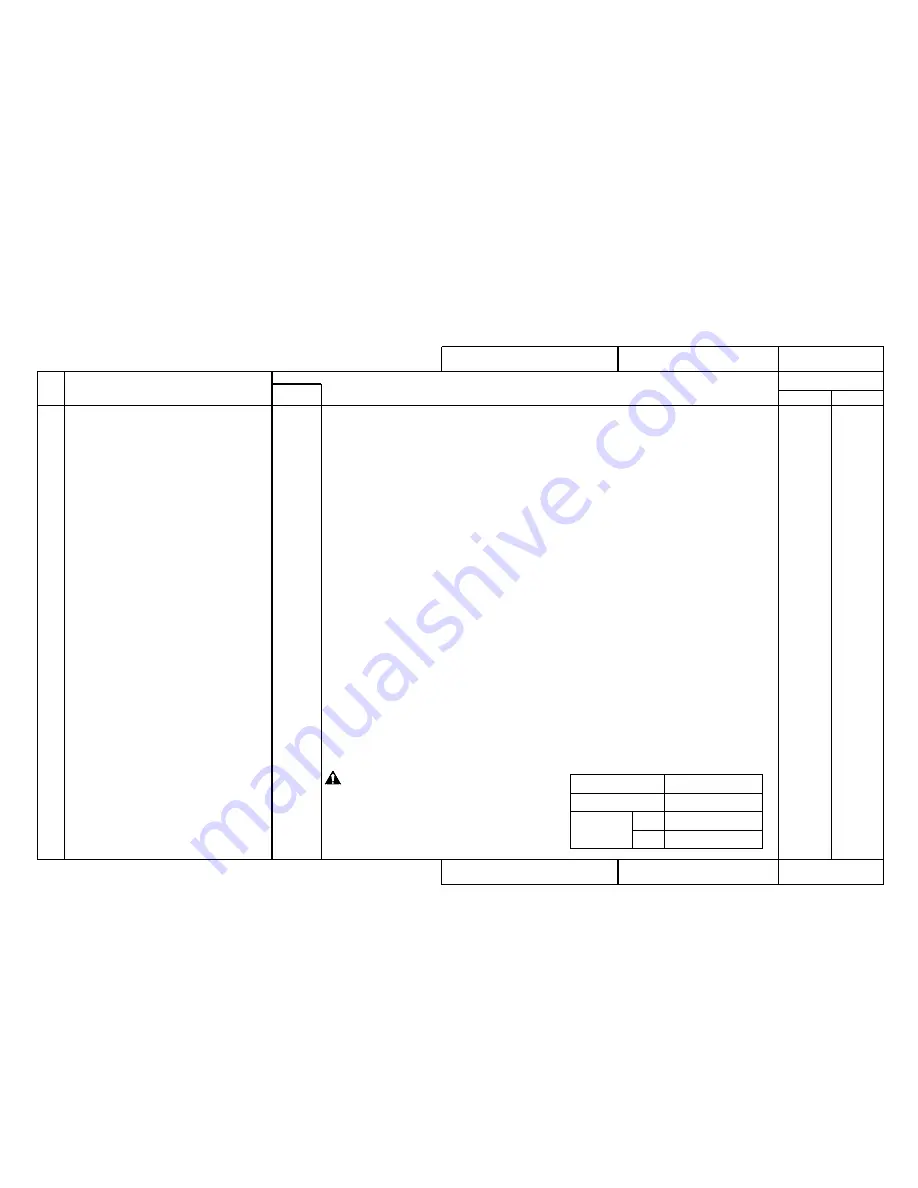
• Media Skew Error

1-1

1-2

1-3

1-4

1-5

1-6

1-7

2-1

• Reload the media and confirm its current status.

If the problem is simply due to poor loading, explain to the user how to load the media properly.

• Are the fans working normally according to the self-diagnostic “Examination: Fans”? 

Check the connectors between fan assembly, fan extension cable assembly and main board
assembly.
Fan extension cable 1 assembly is J115 (FAN1) on the main board assembly
Fan extension cable 2 assembly is J116 (FAN2) on the main board assembly
Fan extension cable 3 assembly is J117 (FAN3) on the main board assembly
Fan extension cable 4 assembly is J118 (FAN4) on the main board assembly

Replace fan assembly.

Replace Fan extension cable 1 assembly, Fan extension cable 2 assembly, Fan extension cable
3 assembly and Fan extension cable 4 assembly. 

• Is the shielding material securely attached in the proper positions?

Shield material GA-A, shield GA-B, shield GA-C

Re-attach in the proper positions.

• Is there a problem with the movement of the pressure lever?

Apply grease (G501) and adjust the pressure transfer plate.

• With the pressure lever lowered, do all pressure rollers make contact with the grid roller?

(Are any of the pressure rollers idling?)

Replace the pressure rollers or the pressure assembly.

• Is there a uniform gap between head and platen?

Use the rail height jig (JD-30395) to adjust the position of the platen.

• Is there distortion or damage to the grid roller?

Replace grid roller.

• After carrying out the adjustments according to the procedure above, run the self-diagnostic “Skew

Verification”.

No.

Symptom

Sequence

Items to be Confirmed

Printer Status Messages

1080

1220

1520

1690

1060

2030

R E P

B A C

G O   T O   R e f .   P a g e s

[ Rated Value ]

Rated Value

Condition

7m

50m

Within 2.5 mm

Within 1.5 mm

Within 10 mm

Cut media

Roll media

CAUTION:

Since this task will establish the
reference position for determin-
ing skew, it should be adjusted
carefully. 

Summary of Contents for Falcon Outdoor 46

Page 1: ...MAINTENANCE MANUAL Eco Solvent Inkjet Printer Rockhopper 46 62 Rockhopper AP 74016 Rev 1 0 ...

Page 2: ...indows 95 Windows NT 3 51 Windows NT 4 0 MS DOS are trademarks or trade names of the Microsoft Corporation Other names of products and companies are the trademarks or trade names of each relevant company This manual contains basic technical details necessary for marketplace servicing to maintain product quality and performance of Model Name Rockhopper 46 62 printer Model Name Rockhopper 46 62 prin...

Page 3: ...n site visit Assemble the necessary maintenance parts from the matrix map At the user s premises first check the symptoms Proceed with maintenance work in accordance with the fault tracing procedure After the repair work is finished be sure to check again by testing in accordance with the test procedure 3 2 If repair is not possible even though all the work has been done in accordance with the fau...

Page 4: ...out drain the waste fluid bottle 1 After head cleaning and initial filling 2 When it was not possible to capture main board assembly backup parameters PRECAUTION 6 Take Care When Inserting Head Cable and Y Cable PRECAUTION 7 Ink and Cleaning Fluid Conduct Electricity When the print head assembly head board assembly and main board assembly have been replaced be careful to insert the head cable and ...

Page 5: ...rinter CON 2000 CON 2000 Contents CON 3001 3 CON 3007 9 How to use the Maintenance Manual CON 4000 CON 4000 Trouble Shooting Lists TRB 0000 TRB 0000 3 Matrix Map MAP 0000 MAP 0000 3 Fault Tracing Procedure EXA 0000 EXA 0000 3 Replacement and Adjustment Procedures REP 0000 REP 0000 3 Fundamental Knowledge GID 0000 GI D 0000 3 Stored Test Patterns PAT 0000 PAT 0000 3 Self Diagnosis Functions BAC 000...

Page 6: ...n Message is not Displayed Trouble with Initialization MAP2000 Trouble with Media Feed MAP3000 Trouble with Printing MAP4000 Problem Involving Noise MAP5000 Trouble with Media Cutting MAP6000 Online Function Problems MAP7000 Other MAP8000 Fault Tracing Procedure EXA0000 When Message is Displayed Printer Status Messages EXA1000 Data Errors EXA1200 Command Errors EXA1250 CPU System Faults EXA1500 Me...

Page 7: ...EP 1260 Maintenance Station Assembly REP 1270 Y Motor Assembly REP 1280 Steel Belt REP 1290 T Fence Assembly REP 1300 Cursor Plate Spring Steel Flexible Guide Assembly REP 1310 Y Return Pulley Assembly REP 1320 Cartridge Frame Assembly REP 1330 Ink ID Sensor Assembly REP 1340 Detector Assembly REP 1350 Y Cable REP 1360 Ink Tubes REP 1370 Cutter Solenoid Assembly REP 1380 Print Head Assembly Head C...

Page 8: ...st error message BAC1070 History Head nozzle ejection count check BAC1070 Head Waveform BAC1080 Adjustment BAC2000 Capping Position Adjustment BAC2010 Skew Verification BAC2030 Head Rank Input Include Initial filling BAC2040 Head Nozzle Verification BAC2050 Left Head Tilt Verification BAC2060 Right Head Tilt Verification BAC2070 Repeatability Printing Positioning BAC2080 CW Adjustment BAC2090 Flus...

Page 9: ... is not Displayed Trouble with Initialization MAP2000 2 Trouble with Media Feed MAP3000 2 Trouble with Printing MAP4000 2 Problem Involving Noise MAP5000 Trouble with Media Cutting MAP6000 Online Function Problems MAP7000 Other MAP8000 Fault Tracing Procedure EXA0000 3 When Message is Displayed Printer Status Messages EXA1000 1020 2 Data Errors EXA1200 Command Errors EXA1250 CPU System Faults EXA1...

Page 10: ...0 Maintenance Station Assembly REP 1270 Y Motor Assembly REP 1280 Steel Belt REP 1290 T Fence Assembly REP 1300 Cursor Plate Spring Steel Flexible Guide Assembly REP 1310 2 Y Return Pulley Assembly REP 1320 Cartridge Frame Assembly REP 1330 Ink ID Sensor Assembly REP 1340 Detector Assembly REP 1350 Y Cable REP 1360 2 Ink Tubes REP 1370 2 Cutter Solenoid Assembly REP 1380 Print Head Assembly Head C...

Page 11: ...st error message BAC1070 History Head nozzle ejection count check BAC1070 Head Waveform BAC1080 Adjustment BAC2000 Capping Position Adjustment BAC2010 Skew Verification BAC2030 Head Rank Input Include Initial filling BAC2040 Head Nozzle Verification BAC2050 Left Head Tilt Verification BAC2060 Right Head Tilt Verification BAC2070 Repeatability Printing Positioning BAC2080 CW Adjustment BAC2090 Flus...

Page 12: ...tenance Manual How to use the Maintenance Manual Como usar el Manual de Mantenimiento l CON4010 How to use the Trouble Shooting Lists TRB CON4020 How to use the Matrix Map MAP CON4040 How to use the Fault Tracing Procedure EXA CON4050 Procedimiento de Reemplazo y Ajustes REP CON4060 Model Name Rockhopper 46 62 ...

Page 13: ...y daily inspection Check error messages check user usage conditions output diagnostic pattern output setup list Retry after changing settings etc Manual de Operaciones Conocimiento báasico Cuidados diarios Mantencion periodica inspeccion Limpieza Task Page Details Reference Materials Gather the necessary maintenance parts Matrix Map MAP Gather the necessary maintenance parts Maintenance Parts list...

Page 14: ... TRB1000 Printer Status Messages Data Errors Command Errors CPU System Faults Mechanical System Faults When Message is Not Displayed TRB2000 to TRB2001 Trouble with Initialization Troubles that occur when unpacking immediately after delivery are grouped here Check this group for a similar trouble occurring other than immediately after delivery Troubles concerning the series of operations up to the...

Page 15: ...plotted Media is not suction Replacement and Adjustment Procedure REP No Name and Diagram Number of Replacement Part DF 41586 Main Board Assembly DF 40097 Panel Board Assembly DF 41617 Panel Cable DF 41590 Cover Switch Assembly DF 41589 Lever Sensor Assembly DF 41595 Edge Sensor Assembly DF 41588 Head Board Assembly DF 41592 XR Cable Assembly Paper Sensor R DF 41600 Y Cable DF 41619 Switch Cable A...

Page 16: ...s on the print head are not inserted obliquely and they are locked securely Insert the connectors again Is there a broken lead in head cables Replace head cables Is the print head assembly damaged Replace the print head assembly Is the head board assembly damaged Replace it Check that the Y cable connector is connected securely and not inserted obliquely Reconnect head board assembly connectors J2...

Page 17: ... and Adjustment Procedure 1 Replacement Procedure 2 Adjustment and Examination Procedure REFERENCE If there is to be no replacement that includes the Y motor assembly steps 2 4 and 5 are not necessary Replace the Y Motor Assembly 1 Remove the Left and Right Covers 2 Remove the Rear Paper Guide 3 Remove the Steel Belt 4 Open the Control Box 5 Disconnect connector J120 YMOT from the Main Board Assem...

Page 18: ...000 Command Errors TRB1000 CPU System Faults TRB1000 Mechanical System Faults TRB1000 When Message is Not Displayed Trouble with Initialization TRB2000 Trouble with Printing TRB2000 Trouble with Media Feed TRB2000 Trouble with Media Cutting TRB2001 Problem Involving Noise TRB2001 Online Function Problems TRB2001 Others TRB2001 Heater System TRB2001 How to Use LEDs to Check CPU System TRB1001 and M...

Page 19: ...1000 Command Errors TRB1000 CPU System Faults TRB1000 Mechanical System Faults TRB1000 When Message is Not Displayed Trouble with Initialization TRB2000 Trouble with Printing TRB2000 Trouble with Media Feed TRB2000 Trouble with Media Cutting TRB2001 Problem Involving Noise TRB2001 Online Function Problems TRB2001 Others TRB2001 Heater System TRB2001 How to Use LEDs to Check CPU System TRB1001 and ...

Page 20: ... Command fetch E 0 1 6 C P U E r r 0 7 Bus error exception Data load E 0 1 6 C P U E r r 0 8 System call exception error E 0 1 6 C P U E r r 0 9 Break point exception error E 0 1 6 C P U E r r 1 0 Reserved command exception error E 0 1 6 C P U E r r 1 1 Unable to use coprocessor exception error E 0 1 6 C P U E r r 1 2 Operation overflow exception error E 0 1 6 C P U E r r 1 3 Trap exception error ...

Page 21: ... C P U E r r 3 3 E237 Error Transfer memory E129 Error NVRAM Standard DRAM error Optional DRAM 1 error Optional DRAM 2 error Interrupt exception error Command boundary exception error Data boundary exception error Address error exception Load or command fetch Address error exception Store Bus error exception Command fetch Bus error exception Data load System call exception error Break point except...

Page 22: ...ished Dots are missing from the printing Cleaning does not cure blockage No imprime nada No imprime un color especifico La superficie entera se imprime en negro Printing becomes shaded The image contains blurs Transverse lines appear to be split AParecen lineas blancas y negras en la impresion Orillas de la impresion aparecen borrosas Many satellites unwanted dots The printing has whiskers Printed...

Page 23: ...40 EXA7050 EXA7060 The printer hangs up Power shutdown during printing The ink cartridges will not go in Ink has overflowed from the waste fluid box Ink overflows from flushing box Ink is split around the X rail Cannot connect normally with Centronics Cannot connect normally with Network The scale function does not work correctly The rotate function does not work correctly The mirror function does...

Page 24: ... CPU System Faults MAP1500 Mechanical System Faults MAP1700 When Message is Not Displayed Trouble with Initialization MAP2000 Trouble with Printing MAP4000 Trouble with Media Feed MAP3000 Trouble with Media Cutting MAP6000 Problem Involving Noise MAP5000 Online Function Problems MAP7000 Other MAP8000 Model Name Rockhopper 46 Model Name Rockhopper 46 Heater System MAP9000 Heaters Fault MAP1800 ...

Page 25: ...aults MAP1500 Mechanical System Faults MAP1700 2 When Message is Not Displayed Trouble with Initialization MAP2000 2 Trouble with Printing MAP4000 2 4001 3 Trouble with Media Feed MAP3000 3 Trouble with Media Cutting MAP6000 2 Problem Involving Noise MAP5000 3 Online Function Problems MAP7000 2 Other MAP8000 2 Model Name Rockhopper 62 Model Name Rockhopper 62 Heater System MAP9000 2 Heaters Fault ...

Page 26: ...and Adjustment Procedure REP No Name and Diagram Number of Replacement Part DF 41586 Main Board Assembly DF 40097 Panel Board Assembly DF 41590 Cover Switch Assembly DF 41617 Panel Cable DF 41589 Lever Sensor Assembly DF 41595 Edge Sensor Assembly DF 41588 Head Board Assembly DF 41592 XR Cable Assembly Paper Sensor R DF 41600 Y Cable DF 40113 Cutter Solenoid Assembly DF 41593 Detector1 Assembly DF...

Page 27: ...ment and Adjustment Procedure REP No Name and Diagram Number of Replacement Part DF 41586 Main Board Assembly DF 40097 Panel Board Assembly DF 41590 Cover Switch Assembly DF 41617 Panel Cable DF 41589 Lever Sensor Assembly DF 41595 Edge Sensor Assembly DF 41588 Head Board Assembly DF 41592 XR Cable Assembly Paper Sensor R DF 41600 Y Cable DF 40113 Cutter Solenoid Assembly DF 41593 Detector1 Assemb...

Page 28: ...ed When Message is Displayed Data Errors Command Errors EXA1230 to EXA1250 Problem Network Detection Error Network Initialization Error MH01 Error Undefined Command MH02 Error Parameter Error MH03 Error Numerical Error MH04 Error Undefined Character Set MH07 Error Buffer Overflow Replacement and Adjustment Procedure REP No Name and Diagram Number of Replacement Part DF 41586 Main Board Assembly Fa...

Page 29: ...4 Address error exception load E016 CPUErr 05 Address error exception store E016 CPUErr 06 Bus error exception check E016 CPUErr 07 Bus error exception load E016 CPUErr 08 System call exception E016 CPUErr 09 Break point exception E016 CPUErr 10 Reserved command exception E016 CPUErr 11 Processor usage denial exception E016 CPUErr 12 Operation overflow exception E016 CPUErr 13 Trap exception E016 ...

Page 30: ...Error E066 Y Motor Error E070 Y Encoder Error E072 Y Timeout Error E074 Y Overcurrent Error E075 Sensor Abnormal Replacement and Adjustment Procedure REP No Name and Diagram Number of Replacement Part DF 41586 Main Board Assembly DF 41597 X Motor Assembly DF 41598 CR Motor Assembly Y Motor DF 41607 T Fence DF 40109 Origin Sensor Assembly DF 41587 Power Board Assembly DF 40173 Vacuum Fan Assembly D...

Page 31: ... Y Motor Error E070 Y Encoder Error E072 Y Timeout Error E074 Y Overcurrent Error E075 Sensor Abnormal Replacement and Adjustment Procedure REP No Name and Diagram Number of Replacement Part DF 41586 Main Board Assembly DF 41597 X Motor Assembly DF 41598 CR Motor Assembly Y Motor DF 41607 T Fence DF 40109 Origin Sensor Assembly DF 41587 Power Board Assembly DF 40173 Vacuum Fan Assembly DF 41620 Fa...

Page 32: ...Replacement Part Front Right Heater Sensor Front Left Heater Sensor Rear Right Heater Sensor Rear Left Heater Sensor 1040 1040 1040 1040 1800 Fault Tracing Procedure EXA No Err F L T Sensor 1800 Err R L T Sensor 1800 Err R R T Sensor 1800 Err FRFLT Sensor 1800 Err FRRLT Sensor 1800 Err FRRRT Sensor 1800 Err FLRLT Sensor 1800 Err FLRRT Sensor 1800 Err RRRLT Sensor 1800 Err 2FRLT Sensor 1800 Err 2FR...

Page 33: ...lacement Part Front Right Heater Sensor Front Left Heater Sensor Rear Right Heater Sensor Rear Left Heater Sensor 1040 2 1040 2 1040 2 1040 2 1800 Fault Tracing Procedure EXA No Err F L T Sensor 1800 Err R L T Sensor 1800 Err R R T Sensor 1800 Err FRFLT Sensor 1800 Err FRRLT Sensor 1800 Err FRRRT Sensor 1800 Err FLRLT Sensor 1800 Err FLRRT Sensor 1800 Err RRRLT Sensor 1800 Err 2FRLT Sensor 1800 Er...

Page 34: ...embly DF 41595 Edge Sensor Assembly DF 41588 Head Board Assembly DF 41592 XR Cable Assembly Paper Sensor R DF 41600 Y Cable DF 41619 Switch Cable Assembly DF 41587 Power Board Assembly DF 41468 DC Cable Assembly DF 41593 Detector 1 Assembly DF 41594 Detector 2 Assembly DF 40106 Detector Assembly Black DF 40107 Detector Assembly Y DF 40146 Detector Assembly M DF 40147 Detector Assembly C DF 41602 C...

Page 35: ...r Assembly DF 41588 Head Board Assembly DF 41592 XR Cable Assembly Paper Sensor R DF 41600 Y Cable DF 41619 Switch Cable Assembly DF 41587 Power Board Assembly DF 41468 DC Cable Assembly DF 41593 Detector 1 Assembly DF 41594 Detector 2 Assembly DF 40106 Detector Assembly Black DF 40107 Detector Assembly Y DF 40146 Detector Assembly M DF 40147 Detector Assembly C DF 41602 Cap Assembly DF 41603 Pump...

Page 36: ...s when it is initialized or during printing The media tears when it is initialized or during printing The media size is different after media mounting and initialization Tracing paper and thin media cannot be detected Replacement and Adjustment Procedure REP No Name and Diagram Number of Replacement Part DF 41586 Main Board Assembly DF 40173 Vacuum Fan Assembly DF 41620 Fan Extension Cable 1 Assem...

Page 37: ...ng printing The media tears when it is initialized or during printing The media size is different after media mounting and initialization Tracing paper and thin media cannot be detected Replacement and Adjustment Procedure REP No Name and Diagram Number of Replacement Part DF 41586 Main Board Assembly DF 40173 Vacuum Fan Assembly DF 41620 Fan Extension Cable 1 Assembly DF 41621 Fan Extension Cable...

Page 38: ...n scanning direction Inaccurate straight line in the direction of head movement straightness Replacement and Adjustment Procedure REP No Name and Diagram Number of Replacement Part DF 41586 Main Board Assembly DF 40173 Vacuum Fan Assembly DF 41620 Fan Extension Cable 1 Assembly DF 41621 Fan Extension Cable 2 Assembly DF 41622 Fan Extension Cable 3 Assembly DF 41605 Ink Tube DF 41601 Head Cable DF ...

Page 39: ...ate straight line in the direction of head movement straightness Replacement and Adjustment Procedure REP No Name and Diagram Number of Replacement Part DF 41586 Main Board Assembly DF 40173 Vacuum Fan Assembly DF 41620 Fan Extension Cable 1 Assembly DF 41621 Fan Extension Cable 2 Assembly DF 41622 Fan Extension Cable 3 Assembly DF 41993 Fan Extension Cable 4 Assembly DF 41605 Ink Tube DF 41601 He...

Page 40: ... Procedure REP No Name and Diagram Number of Replacement Part DF 41586 Main Board Assembly DF 40173 Vacuum Fan Assembly DF 41620 Fan Extension Cable 1 Assembly DF 41621 Fan Extension Cable 2 Assembly DF 41622 Fan Extension Cable 3 Assembly DF 41529 Pressure Assembly DF 40854 Cursor Plate Spring DF 41616 Steel Flexible Cable Assembly DF 41840 Grid Roller Assembly DF 41841 Speed Reduction Pulley Ass...

Page 41: ... Number of Replacement Part DF 41586 Main Board Assembly DF 40173 Vacuum Fan Assembly DF 41620 Fan Extension Cable 1 Assembly DF 41621 Fan Extension Cable 2 Assembly DF 41622 Fan Extension Cable 3 Assembly DF 41993 Fan Extension Cable 4 Assembly DF 41529 Pressure Assembly DF 40854 Cursor Plate Spring DF 41616 Steel Flexible Cable Assembly DF 41840 Grid Roller Assembly DF 41988 Speed Reduction Pull...

Page 42: ...media is fed Abnormal noise when cutting Replacement and Adjustment Procedure REP No Name and Diagram Number of Replacement Part DF 41586 Main Board Assembly DF 40173 Vacuum Fan Assembly DF 41587 Power Board Assembly DF 40690 Print Head Assembly Colour DF 41588 Head Board DF 40144 Y Return Pulley Assembly DF 41598 Cursor Motor Assembly Y Motor DF 41529 Pressure Assembly DF 40137 X Speed Reduction ...

Page 43: ...a is fed Abnormal noise when cutting Replacement and Adjustment Procedure REP No Name and Diagram Number of Replacement Part DF 41586 Main Board Assembly DF 40173 Vacuum Fan Assembly DF 41587 Power Board Assembly DF 40690 Print Head Assembly Colour DF 41588 Head Board DF 40144 Y Return Pulley Assembly DF 41598 Cursor Motor Assembly Y Motor DF 41529 Pressure Assembly DF 40137 X Speed Reduction Belt...

Page 44: ...g operation is normal but the media is not cut The cutting is bad and the media jams The cutting operation is normal but the media does not fall out Inaccurate media cutting Cutting is delayed for some time after printing has ended White paper is cut Replacement and Adjustment Procedure REP No Name and Diagram Number of Replacement Part DF 41586 Main Board Assembly DF 40113 Cutter Solenoid Assembl...

Page 45: ...ing operation is normal but the media is not cut The cutting is bad and the media jams The cutting operation is normal but the media does not fall out Inaccurate media cutting Cutting is delayed for some time after printing has ended White paper is cut Replacement and Adjustment Procedure REP No Name and Diagram Number of Replacement Part DF 41586 Main Board Assembly DF 40113 Cutter Solenoid Assem...

Page 46: ...es not work correctly The rotate function does not work correctly The mirror function does not work correctly Other functions are not working correctly Printing position is offset Some data are not printed omitted Text and printing data are garbled extra lines appear There is an extra feed after printing is finished Replacement and Adjustment Procedure REP No Name and Diagram Number of Replacement...

Page 47: ...does not work correctly The rotate function does not work correctly The mirror function does not work correctly Other functions are not working correctly Printing position is offset Some data are not printed omitted Text and printing data are garbled extra lines appear There is an extra feed after printing is finished Replacement and Adjustment Procedure REP No Name and Diagram Number of Replaceme...

Page 48: ...s split around the X rail Replacement and Adjustment Procedure REP No Name and Diagram Number of Replacement Part DF 41586 Main Board Assembly DF 40127 Cartridge Frame Assembly DF 41593 Detector 1 Assembly DF 41594 Detector 2 Assembly DF 40106 Detector Assembly Black DF 40107 Detector Assembly Y DF 40146 Detector Assembly M DF 40147 Detector Assembly C DF 41587 Power Board Assembly DF 41591 Waste ...

Page 49: ...d from the waste fluid bottle Replacement and Adjustment Procedure REP No Name and Diagram Number of Replacement Part DF 41586 Main Board Assembly DF 40127 Cartridge Frame Assembly DF 41593 Detector 1 Assembly DF 41594 Detector 2 Assembly DF 40106 Detector Assembly Black DF 40107 Detector Assembly Y DF 40146 Detector Assembly M DF 40147 Detector Assembly C DF 41587 Power Board Assembly DF 41591 Wa...

Page 50: ...en Message is Not Displayed When Message is Not Displayed Heater system EXA9000 Problem Heater does not stop warming up or is broken Replacement and Adjustment Procedure REP No Name and Diagram Number of Replacement Part Front Heater Rear Heater Front Heater Sensor Rear Heater Sensor 1040 1040 1040 1040 9000 Fault Tracing Procedure EXA No ...

Page 51: ... Message is Not Displayed When Message is Not Displayed Heater system EXA9000 Problem Heater does not stop warming up or is broken Replacement and Adjustment Procedure REP No Name and Diagram Number of Replacement Part Front Heater Rear Heater Front Heater Sensor Rear Heater Sensor 1040 2 1040 2 1040 2 1040 2 9000 Fault Tracing Procedure EXA No ...

Page 52: ...ata Errors EXA1200 Command Errors EXA1250 CPU System Faults EXA1500 Mechanical System Faults EXA1700 When Message is Not Displayed Trouble with Initialization EXA2000 Trouble with Printing EXA4000 Trouble with Media Feed EXA3000 Trouble with Media Cutting EXA6000 Problem Involving Noise EXA5000 Online Function Problems EXA7000 Other EXA8000 Fault Tracing Procedure Heater System EXA9000 Heaters Sys...

Page 53: ...A1250 CPU System Faults EXA1500 Mechanical System Faults EXA1700 When Message is Not Displayed Trouble with Initialization EXA2000 2070 2 Trouble with Printing EXA4000 4050 2 4100 2 4130 2 Trouble with Media Feed EXA3000 3000 2 Trouble with Media Cutting EXA6000 Problem Involving Noise EXA5000 Online Function Problems EXA7000 Other EXA8000 Difference between Rockhopper 46 and 62 Fault Tracing Proc...

Page 54: ...se G 501 to the elongated round hole in the pressure relay plate Refer to CAT4000 Is the lever sensor assembly fitted securely Related to raising and lowering the pressure lever Adjust the lever sensor assembly fitting position Is the sensor unit in the lever sensor assembly dirty Related to raising and lowering the pressure lever Clean the sensor unit with cotton swabs Is the lever sensor assembl...

Page 55: ...onfirm the amount of sensor reflec tion Using thick coated paper check whether the paper detection value is within 0090 to 00a4 Replace edge sensor assembly Adjust with the head board assembly variable resistor VR1 Check Y cable contacts Check that they are not inserted obliquely Reconnect main board assembly connector J111 HEAD1 and head board assembly connector J201 MAIN1 The head board assembly...

Page 56: ...le 4 assembly Is the shielding material securely attached in the proper positions Shield material GA A shield GA B shield GA C Re attach in the proper positions Is there a problem with the movement of the pressure lever Apply grease G501 and adjust the pressure transfer plate With the pressure lever lowered do all pressure rollers make contact with the grid roller Are any of the pressure rollers i...

Page 57: ...onnect it securely to connector J107 XR on the main board assembly Use the printer s self diagnostic Sensor Edge to confirm the amount of sensor reflec tion Using thick coated paper check whether the paper detection value is within 0090 to 00a4 Replace edge sensor assembly The head board assembly may be damaged Replace it Check with the printer s self diagnostic Sensor X Rear whether the sensor is...

Page 58: ...move ment of the pressure lever appears to be chattering when the lever is moved slowly up and down Check the lever sensor assembly contact Reconnect main board assembly connector J104 LEVER If there seems to be chattering the sensor may be faulty Replace the lever sensor assembly Is the cable of the XR cable assembly rear paper sensor that is attached below the rear paper guide connected securely...

Page 59: ... switch on again Use the printer s self diagnostic Sensor X Rear to make sure that the media end detec tion is working normally Cover the paper sensor R XR cable assembly with media and confirm that SENS Xr Paper On is displayed Check the paper sensor R contact Reconnect main board assembly connector J107 XR If Media Present does not appear the sensor may be faulty Replace the paper sensor R assem...

Page 60: ...it does not fall the cutter may be faulty Replace the cutter Use the printer s self diagnostic Aging Cutter to confirm the up and down movement of the sole noid No Symptom Sequence Items to be Confirmed When Message is Displayed Printer Status Messages Refer to the Operation Manual Basic Manual Refer to the Operation Manual Basic Manual R E P B A C G O T O R e f P a g e s Moves up down Check the d...

Page 61: ...replace Y cable b Try fitting a new solenoid assembly Check for continuity between connectors If there is up down movement replace solenoid assembly c Try replacing the head board assembly Reference after replacement use the printer s EXAM Sensor self diagnostic Edge to adjust the amount of sensor reflection The adjustment volume is on the head board d Try replacing the main board assembly Referen...

Page 62: ...s been extended the value Standard memory 8 MB Extended memory will be displayed If two 36 MB SIMMs have been installed 80 MB is displayed With Iris 46 WIDE since a 16 MB SIMM has been added in Slot 1 the display is nor mally 24 MB Optional Memory MB shown in the Setup List is the amount of extended memory only If there is a difference between the actual memory capacity and the memory capac ity sh...

Page 63: ...of the ink ID sensor assembly that is shown as being faulty with the position of any one of J406 to J409 J412 and J413 on the junction board assembly that appears to be normal If after re inserting the connectors a different ink cartridge unit now appears to be faulty it means that the ink ID sensor assembly that was shown as being faulty is damaged Replace the faulty ink ID sensor assembly If aft...

Page 64: ... change move to the next step Exchange the position of the connector of the ink detector assembly for the ink for which Ink Low or No Ink is indicated with the position of any one of J402 to J405 J410 and J411 on the junction board assembly that appears to be normal If after re inserting the connectors a different ink now appears to be No Ink it means that the detector assembly is damaged Replace ...

Page 65: ... No Cartridge the following is displayed when all cartridges are removed and the following is displayed when the switch that detects whether the black cartridge is present is pressed Sensor No Cartridge KCMYOG CAUTION Take care You can be hurt by the ink filling needle when you operate the switch showing whether there is ink in the cartridge frame assembly For safety work with the cartridge cover ...

Page 66: ...dge appears or No Cartridge is shown for all cartridges the damage may be between the junction board assembly and the main board assembly Reference Take care when you are replacing the detector assembly that senses whether there is a cartridge present It can become damaged by over tightening the attaching screw Check the ink ID cable contacts Reconnect junction board assembly connector J401 INK ID...

Page 67: ...rst Check whether the parameters are set to the initial values by running the printer s self diagnostic Adjust Test print to output the parameters that have been set Refer to the functions and operations manual for the initial values of parameters If the parameters have been restored to their initial values please contact the Inquiry desk and quote your printer serial number to obtain a setup list...

Page 68: ...al filling with the printer s self diagnos tic Adjust Enter Rank With the specified cartridge inserted securely use the printer s self diagnostic mode Sensor Cartridge to check whether the status of the special cartridge is operating nor mally For checking use the Insert Special Cartridge procedure shown in EXA1080 After adjustment and replacement carry out initial filling with the printer s self ...

Page 69: ... detection is working normally Slowly remove and replace the waste fluid bottle to confirm that the present absent dis play appears If the display is not normal the sensor position may be faulty Adjust the position of the waste fluid bottle detection switch assembly Make sure the waste liquid bottle is making contact Reconnect main board assembly connector J105 INK TANK The waste fluid bottle dete...

Page 70: ...move and replace the waste fluid bottle to confirm that the present absent dis play appears If the display is not normal the sensor mounting position may be at fault Adjust the mounting position of the waste fluid bottle detection switch assembly Make sure the waste liquid bottle is making contact Reconnect main board assembly connector J105 INK TANK The waste fluid bottle detection switch assembl...

Page 71: ...olvent type ink cartridge installed W Wash fluid cartridge installed N Other ink cartridge installed Make sure the detector assembly connector is making contact Reconnect junction board assembly connectors J406 INK ID Sensor1 BK J407 INK ID Sensor2 C J408 INK ID Sensor3 M J409 INK ID Sensor4 Y J412 INK ID Sensor5 J413 INK ID Sensor6 If there is no change move to the next step Check the ink ID cabl...

Page 72: ... can not be detected Network Initialization Error An error has occurred during the optional network board initialization operation 1 1 1 2 The main board assembly may be damaged Replace it The Ethernet board assembly may be damaged Replace it Go to MAP1200 No Symptom Sequence Items to be Confirmed When Message is Displayed Data Errors 1140 R E P B A C G O T O R e f P a g e s ...

Page 73: ...cter set is present MH07 Error Buffer Overflow The polygon buffer or the download able character buffer has overflowed 1 1 1 2 1 3 1 4 Try communicating with the available computer and cable Contact your Mutoh distributor Is there any record of an error in the printing data Try changing the type of application driver If the symptoms persist despite various application driver changes Obtain the pri...

Page 74: ...ain board assembly may be damaged Replace it This error may occur when there is dust etc in extended memory slot 1 or slot 2 Use an air duster to remove the dust and reinstall Install reliable memory of the same capacity and check with the self diagnostic Examination Memory Capacity Replace optional memory The main board assembly may be damaged Replace it No Symptom Sequence Items to be Confirmed ...

Page 75: ...6 CPU Err 06 Bus error exception Command check Indicates that a bus error has occurred when loading or storing a command E016 CPU Err 07 Bus error exception Data load Indicates that a bus error has occurred when loading or storing a command E016 CPU Err 08 System call exception error Indicates that a system call has caused an error E016 CPU Err 09 Break point exception error Indicates that a break...

Page 76: ...rror Indicates that the watch has caused an error E016 CPU Err 32 Watchdog timeout exception error Indicates that a watchdog timeout has occurred E016 CPU Err 33 Abort error Indicates that an abort has occurred E237 Err Transfer Memory Transfer memory error Transfer memory access error Indicates that a fault has occurred in transferring printing data that has been analysed 1 1 1 2 1 3 1 4 Check AC...

Page 77: ...Displayed 1 E129 Error NVRAM This message indicates that a fault has occurred in the NVRAM on the Main board that records printer set tings 1 1 The main board assembly may be damaged Replace it No Symptom Sequence Items to be Confirmed When Message is Displayed CPU System Faults 1140 R E P B A C G O T O R e f P a g e s ...

Page 78: ...rcurrent This message indicates that a fault has occurred due to an overload of the media feed X axis motor while the printer was working 1 1 1 2 1 3 1 4 1 5 1 6 Use the self diagnostic Examination History to check the history of faults Use the self diagnostic Aging Media Feed Motor with a setting of 50 times to check whether the X Motor error occurs Check connectors J119 X MOT and J121 X ENC on t...

Page 79: ...tic Aging Carriage Motor with a setting of 50 times to check whether the Y Motor error occurs Check cable connector J120 Y MOT on the main board Check whether the timing fence T fence is dirty or twisted If there is grease or dirt on the fence wipe it away with a dry cloth If there is ink on the fence wet a cloth with neutral cleaner and wipe lightly If the T fence is severely soiled and can not b...

Page 80: ...he main board assembly and J201 MAIN1 on the head board assem bly Insert them properly Replace the Y cable between J111 HEAD1 and J201 MAIN1 The origin sensor assembly may be faulty Replace it The main board assembly may be damaged Replace it No Symptom Sequence Items to be Confirmed When Message is Displayed Mechanical System Faults 1360 1450 1140 1040 R E P B A C G O T O R e f P a g e s CAUTION ...

Page 81: ...Message is Displayed on LCD heater Heater System Faults 1040 1040 1040 1040 1040 1040 R E P B A C G O T O R e f P a g e s Err F L T Sensor Err R R T Sensor Err R L T Sensor Err FRFLT Sensor Are Front Right and Rear Left Temperature Sensor not connected broken Reconnect sensors replace the Front Rear Paper Guide Are Front Right and Rear Right Temperature Sensor not connected broken Reconnect sensor...

Page 82: ...d broken Reconnect sensors replace the Rear Paper Guide Are two Rear and Front Left Temperature Sensors not connected broken Reconnect sensors replace the Rear Paper Guide Are all Temperature Sensors not connected broken Reconnect sensors replace the Front Paper Guide I No Symptom Sequence Items to be Confirmed When Message is Displayed on LCD Heater Heater System Faults 1040 1040 1040 1040 1040 1...

Page 83: ...is Displayed on LCD heater Heater System Faults 1040 2 1040 2 1040 2 1040 2 1040 2 1040 R E P B A C G O T O R e f P a g e s Err F L T Sensor Err R R T Sensor Err R L T Sensor Err FRFLT Sensor Are Front Right and Rear Left Temperature Sensor not connected broken Reconnect sensors replace the Front Rear Paper Guide Are Front Right and Rear Right Temperature Sensor not connected broken Reconnect sens...

Page 84: ...oken Reconnect sensors replace the Rear Paper Guide Are two Rear and Front Left Temperature Sensors not connected broken Reconnect sensors replace the Rear Paper Guide Are all Temperature Sensors not connected broken Reconnect sensors replace the Front Paper Guide I No Symptom Sequence Items to be Confirmed When Message is Displayed on LCD Heater Heater System Faults 1040 2 1040 2 1040 2 1040 2 10...

Page 85: ...ble connectors on the panel board assembly and main board assembly Check that they are not inserted obliquely and that they are securely locked Reconnect main board assembly connector J110 PANEL and panel board assembly connector J301 MAIN The panel cable may be faulty Replace it Is there a fault in the panel board assembly liquid crystal display Replace the panel board assembly The main board ass...

Page 86: ... Replace the lever sensor assembly With the specified cartridge inserted securely use the printer s self diagnostic mode Sensor No Ink or Sensor No Cartridge to check whether the presence of ink and cartridge are being detect ed normally Check using EXA1100 65YMCK No Cartridge procedure After adjustment or replacement implement initial filling with the printer s self diagnostic Adjust Head Rank Wi...

Page 87: ...r all four black and colour ink tubes Remove the Y Rail cover and cartridge cover and check the flexible cable keeper unit under the head board assembly and the sides of the cartridge Is there an air leak in the damper assembly shield unit Replace the damper assembly and check that ink flows during the cleaning action If ink flows carry out initial filling Are the ink tubes damaged inside the pump...

Page 88: ...assembly damaged Replace the print head assembly Is the head board assembly damaged Replace it Check that the Y cable connector is connected securely and not inserted obliquely Reconnect head board assembly connectors J201 MAIN1 and J202 MAIN2 and main board assembly connectors J111 HEAD1 and J112 HEAD 2 Is there a broken lead in Y cables Replace Y cables The main board assembly may be damaged Rep...

Page 89: ...securely locked Reconnect the main board assembly connector J110 PANEL and the panel board assembly J301 MAIN Replace them With the hold lever down is the liquid crystal display showing lever up Check the lever sensor connector J104 LEVER on the main board assembly Replace the lever sensor assembly Check J104 LEVER cable connection on the main board assembly Re insert it Replace the lever sensor a...

Page 90: ...executed Media is mounted but the initialization operation is not done Printer does not work even with the cover closed Printer does not stop even with the cover opened 1 9 1 10 Is the DC cable assembly connected properly to J001 on the power board assembly and J101 MAIN POWER on the main board assembly See EXA2000 Reconnect it Replace it The main board assembly may be damaged Replace it No Sympto...

Page 91: ...g with the printer s self diagnos tic Adjust Head Rank With the specified cartridge inserted securely use the printer s self diagnostic mode Sensor Cartridge to check whether the status of the special cartridge is operating nor mally Check using EXA1080 Insert special cartridge procedure After adjustment or replacement implement initial filling with the printer s self diagnos tic Adjust Head Rank ...

Page 92: ...cable connectors Check that they are inserted obliquely and securely locked Reconnect main board assembly connector J110 PANEL and panel board assembly connector J301 MAIN Replace the panel cable The panel board assembly may be damaged Replace the panel board assembly The main board assembly may be damaged Replace the main board assembly No Symptom Sequence Items to be Confirmed When No Error is D...

Page 93: ...Printer s Liquid Crystal Display 1 Data is received but not printed 1 1 For checking use Cannot connect normally with Centronics or Ethernet Board proce dures shown in EXA7000 No Symptom Sequence Items to be Confirmed When No Error is Displayed on the Printer s Liquid Crystal Display Trouble with Initialization R E P B A C G O T O R e f P a g e s ...

Page 94: ...the self diagnostic test Check the connectors between fan assembly fan extension cable assembly and main board assembly Fan extension cable 1 assembly is J115 FAN1 on the main board Fan extension cable 2 assembly is J116 FAN2 on the main board Fan extension cable 3 assembly is J117 FAN3 on the main board Replace fan assembly Replace fan extension cable 1 3 Is shielding material fixed securely in t...

Page 95: ...k the connectors between fan assembly fan extension cable assembly and main board assembly Fan extension cable 1 assembly is J115 FAN1 on the main board Fan extension cable 2 assembly is J116 FAN2 on the main board Fan extension cable 3 assembly is J117 FAN3 on the main board Fan extension cable 4 assembly is J118 FAN4 on the main board Replace fan assembly Replace fan extension cable 1 4 Is shiel...

Page 96: ...place fan extension cable 1 3 Is shielding material fixed securely in the specified places Shield GA A Shield GA B Shield GA C Refit shielding securely When the pressure lever is raised and lowered does the pressure unit move up and down smooth ly at the same time Apply grease G 501 if it does not move smoothly Is the pressure roller pressing on the media over its entire length With the pressure l...

Page 97: ...n cable 4 assembly is J117 FAN4 on the main board Replace fan assembly Replace fan extension cable 1 4 Is shielding material fixed securely in the specified places Shield GA A Shield GA B Shield GA C Refit shielding securely When the pressure lever is raised and lowered does the pressure unit move up and down smooth ly at the same time Apply grease G 501 if it does not move smoothly Is the pressur...

Page 98: ... Sensor Edge to confirm the amount of sensor reflec tion Using thick coated paper check whether the paper detection value is within 0090 to 00a4 Check edge sensor connector and head board assembly connector J204 PEDGE Adjust the detection value with the head board assembly variable resistor Replace edge sensor assembly Check the Y cable connectors Check that they are not inserted obliquely Reconne...

Page 99: ...ontinuously 1 1 1 2 1 3 Is there a problem with the printer driver software Upgrade the printer driver version Is there a problem with the program ROM Upgrade the version The main board assembly may be damaged Replace it No Symptom Sequence Items to be Confirmed When No Error is Displayed on the Printer s Liquid Crystal Display Trouble with Printing 1140 R E P B A C G O T O R e f P a g e s ...

Page 100: ...e self diag nostic sensor test Check the connections of XR cable assembly and main board assembly J107 XR Replace XR cable assembly Is there a problem with the printer driver software Upgrade the printer driver version Is there a problem with the program ROM Upgrade the version The main board assembly may be damaged Replace it No Symptom Sequence Items to be Confirmed When No Error is Displayed on...

Page 101: ... the cap assembly spring fallen out or broken If it has fallen out refit it If it is broken replace the cap assembly of the maintenance station assembly Is the capping position correct Adjust the capping position carry out strong cleaning and try again What is the condition of the wiper section Dampen the accessory cleaning cloth slightly with clean water and use it to wipe the surface of the clea...

Page 102: ...ouching If they are touching adjust them If adjustment is not effective replace both the head board assembly and the T fence Are the tubes crushed inside the pump assembly Replace the pump assembly and check the ink flow If it is good carry out initial filling Is the print head assembly damaged Replace the obstructed print head assembly The main board assembly may be damaged Replace it No Symptom ...

Page 103: ... cartridge unit or the SUS pipe connectors Bk Y M C Lm and Lc Check that the O rings are fitted properly Remove the head cover and check the damper Remove the Y Rail cover and cartridge cover and check the flexible cable keeper unit under the head board assembly and the sides of the cartridge Is there an air leak in the damper assembly shield unit Replace the damper assembly and check that ink flo...

Page 104: ... it Is the print head assembly damaged Replace the print head assembly Is the pump motor turning during the cleaning action Check the pump motor cable connector J102 on the main board Replace the pump motor If the pump motor does not turn after performing the above tasks replace the main board assembly Was there any gear damage or mismatching of gears during the cleaning operation Replace the pump...

Page 105: ...rd assembly connectors J201 MAIN1 and J202 MAIN Replace both Y cables The head board assembly may be damaged Replace it The head head assembly may be damaged Replace the print head assembly The main board assembly may be damaged Replace it No Symptom Sequence Items to be Confirmed When No Error is Displayed on the Printer s Liquid Crystal Display Trouble with Printing 1390 1360 1420 1390 1140 R E ...

Page 106: ... Shield material GA A shield material GA B shield material GA C Re attach in the proper positions If the media in question is roll media does the scroller rotate smoothly Adjust the position of the scroller support rollers Replace any roller that is damaged or that moves badly Is the X speed reduction belt tension adjusted to the prescribed value 41 2 N 4 2 kg 0 2 Kg What is the condition of the w...

Page 107: ... board Replace fan assembly Replace Fan extension cables 1 4 Is the shielding material securely attached in the proper positions Shield material GA A shield material GA B shield material GA C Re attach in the proper positions If the media in question is roll media does the scroller rotate smoothly Adjust the position of the scroller support rollers Replace any roller that is damaged or that moves ...

Page 108: ...here any mismatching of gears during the cleaning operation Replace the maintenance station assembly Is the cap assembly spring fallen out or broken If the part has fallen out refit it Replace the cap assembly or the maintenance station assembly Are the tubes crushed inside the pump assembly Replace the pump assembly and check the ink flow If it is good carry out initial filling CAUTION Wait at le...

Page 109: ...tment or replacement implement initial filling with the printer s self diagnostic Adjust Head Rank CAUTION Wait at least 30 minutes after initial filling before printing Printing quality can not be assured unless ink filling has been stabilized The main board assembly may be damaged Replace it The head board assembly may be damaged Replace it No Symptom Sequence Items to be Confirmed When No Error...

Page 110: ...guaranteed Please use recommended media Does the head that is fitted have a rank that is different from the recorded rank Re enter the rank of the print head correctly Check that the T fence and Encoder behind the head board assembly are not touching If they are touching adjust them If adjustment is not effective replace both the head board assembly and the T fence The main board assembly may be d...

Page 111: ...illing has been stabilized Is the steel belt tension adjusted properly 0 98 N 100 g 20 g Make sure the encoder and T fence mounted on the back of the head board assembly are not touching If they are touching adjust them If adjustment does not solve the problem replace both the head board assembly and the fence Is there a loose set screw on the Y drive pulley Re tighten the set screw Is the capping...

Page 112: ...r damage to the gears or transfer gear shaft Replace the maintenance station assembly Has the cap assembly spring fallen out or been broken If a part has fallen out refit it Replace the cap assembly or maintenance station assembly Has ink dried on the surface of the print head and inside the nozzles Use the self diagnostic Adjustment Head Cleaning to clean the print head carry out initial fill ing...

Page 113: ...r the rank of the print head correctly Is the problem with the head tilt adjustment Adjust it Is there a problem with the reciprocal printing position alignment Adjust it Is there a problem with the CW adjustment Adjust it Make sure the encoder and fence mounted on the back of the head board assembly are not touching If they are touching adjust them If adjustment does not solve the problem replace...

Page 114: ...nsion adjusted properly 0 98 N 100 g 20 g Re adjust steel belt tension Is the timing fence dirty or has foreign matter stuck to it Clean it Replace if soiling is not removed by washing or if there is damage Is the Y drive pulley set screw loose Re tighten the set screw securely The internal processing operation of the main board may be faulty Initialize re enter or re adjust the parameters and try...

Page 115: ... pulley set screw loose Replace the X motor assembly Is the X speed reduction belt tension adjusted to the prescribed value 41 2 N 4 2 kg 0 2 kg Readjust the X speed reduction belt tension If the media in question is roll media does the scroller rotate smoothly Adjust the position of the scroller support rollers Replace any roller that is damaged or that moves badly Is the pressure roller pressing...

Page 116: ...e proper positions Is the X drive pulley set screw loose Replace the X motor assembly Is the X speed reduction belt tension adjusted to the prescribed value 41 2 N 4 2 kg 0 2 kg Readjust the X speed reduction belt tension If the media in question is roll media does the scroller rotate smoothly Adjust the position of the scroller support rollers Replace any roller that is damaged or that moves badl...

Page 117: ...ssure lever down does the pressure rollers idle or contact the platen on one side With the pressure lever down is the blade pressing firmly on the media If there are paper dust or scraps near the pressure roller wipe with soft damp cloth If necessary replace pressure assembly pressure rollers and blade If the gap between platen and blade is less than 0 2 mm adjust platen height Is the rough surfac...

Page 118: ...ve pulley set screw loose Replace it Is there a problem with the reciprocal printing position alignment Adjust it Is there a problem with the CW adjustment Adjust it Is the T fence dirty Clean it Replace if soiling is not removed by washing or if there is damage Although the step pattern of the self diagnostic Head Nozzle Check is well adjusted if the vertical lines of the Black Head Tilt Check do...

Page 119: ...essing on the media over its entire length With the pressure lever up does the pressure rollers seem reluctant to turn With the pressure lever down does the pressure rollers idle or contact the platen on one side With the pressure lever down is the blade pressing firmly on the media If there are paper dust or scraps near the pressure roller wipe with soft damp cloth If necessary replace pressure a...

Page 120: ...e proper positions Is the pressure roller pressing on the media over its entire length With the pressure lever up does the pressure rollers seem reluctant to turn With the pressure lever down does the pressure rollers idle or contact the platen on one side With the pressure lever down is the blade pressing firmly on the media If there are paper dust or scraps near the pressure roller wipe with sof...

Page 121: ...e attach in the proper positions Are the rotating fins of the suctions fans touching the cable or are there paper scraps and foreign matter Remove obstructions and foreign matter Check for a broken cable and connections Replace any parts that are broken The fan itself may be faulty Replace it The main board assembly may be faulty Replace it The power board assembly may be faulty Replace it No Symp...

Page 122: ...ouching or some foreign matter at the place producing the abnormal noise Remove the obstruction or foreign matter It a board producing the noise Replace the board assembly in question Power board assembly Main board assembly Head board assembly Print head assembly No Symptom Sequence Items to be Confirmed When No Error is Displayed on the Printer s Liquid Crystal Display Problem Involving Noise 11...

Page 123: ... the noise is coming from between the steel flexible belt and the tube guide replace the tube guide assembly Check whether the cable connected to the head board on the carriage is touching the cover Also check whether is it touching the encoder and fence mounted at the back of the head board If adjusting the position does not solve the problem replace it Is the noise coming from the Y pulley box a...

Page 124: ...tion belt out of tooth with the X speed reduction pulley Replace the X speed reduction belt Is the noise coming from the X motor Replace it Is the rough surface of the grid roller worn in some places Is the grid roller heavy to turn Or does it not turn smoothly Use a nylon brush to clean away any paper dust or paper scraps from the grid roller Adjust platen height or refit the rear paper guide Rep...

Page 125: ...efit the spring and remove any foreign matter Is there foreign matter in the cutter groove and front surface of the printing board section Remove the foreign matter Is the cutter blade parallel with the printing board cutter groove Adjust it The cutter itself may be no good Replace it The head board assembly may be damaged Replace it The Y cable may be damaged Replace it The power assembly board m...

Page 126: ...t Check the connections on cutter solenoid assembly connector and head board assembly con nector J206 SOL If there is no up and down movement the solenoid may be damaged Replace the cutter solenoid assembly Check the Y cable connectors Check that they are not inserted obliquely Re insert the main board assembly connector J111 HEAD1 and the head board assembly con nector J201 MAIN1 Replace them The...

Page 127: ...in board assembly connector J111 HEAD1 and the head board assem bly J201 MAIN1 Replace them The head board assembly may be damaged Replace it The main board assembly may be damaged Replace it No Symptom Sequence Items to be Confirmed When No Error is Displayed on the Printer s Liquid Crystal Display Trouble with Media Cutting 1360 1420 1140 R E P B A C G O T O R e f P a g e s Direction of media fe...

Page 128: ...nsultation Replace the cutter Is the cutter blade chipped or deteriorated as checked in the primary consultation Replace the cutter Has the cutter cap been fixed securely on the top of the cutter as a result of checking in the primary consultation Refit it Is there foreign matter in the cutter groove and on the surface of front paper guide Remove the foreign matter Remove paper dust from the cutte...

Page 129: ...eet media this item applies only to roll media 1 1 1 2 Are paper guide surfaces being cleaned daily Clean the surfaces There may be a static charge on the front paper guide or media Make a proper earth connection Check the humidity of the usage environment and bring it within usage environment specifications No Symptom Sequence Items to be Confirmed When No Error is Displayed on the Printer s Liqu...

Page 130: ...ltation Refit it Does the cutter move up and down smoothly Refit the spring and remove any foreign matter Is there foreign matter in the cutter groove and front surface of the printing board section Remove the foreign matter Remove paper dust from the cutter groove Is the cutter blade parallel with the printing board cutter groove Adjust it The cutter itself may be no good Replace it No Symptom Se...

Page 131: ... 4 Are internal sample prints output without trouble Refer to EXA4030 Does not print at all Is there a problem with the printer driver software Upgrade the printer driver version Is there a problem with the program ROM Upgrade the version The main board assembly may be damaged Replace it No Symptom Sequence Items to be Confirmed When No Error is Displayed on the Printer s Liquid Crystal Display Tr...

Page 132: ...s make sure of the type of cable that is to be used for the connection envi ronment For direct connection of one host and one printer Use a cross cable 100 10Base T For connection of several hosts and one printer through a hub Use a straight cable 100 10Base T To check connections to the network board use the board accessory setup utilities or connect directly to the computer using a crossed cable...

Page 133: ...es not work cor rectly Other functions are not working cor rectly 1 1 1 2 1 3 Is there a problem with the printer driver software Upgrade the printer driver version Is there a problem with the program ROM Upgrade the version The main board assembly may be damaged Replace it No Symptom Sequence Items to be Confirmed When No Error is Displayed on the Printer s Liquid Crystal Display Online Function ...

Page 134: ...head distance or the cutter to head distance causing a problem for top and bottom margin distance adjustments Adjust them Is there a problem with the printer driver software Upgrade the printer driver version Is there a problem with the program ROM Upgrade the version The main board assembly may be damaged Replace it No Symptom Sequence Items to be Confirmed When No Error is Displayed on the Print...

Page 135: ...is no good check the cable connections of J112 HEAD2 on the main board assembly and J202 MAIN2 on the head board assembly Replace the T fence Replace the Y motor assembly Replace the head board assembly Replace the Y cable between J112 HEAD2 on the main board assembly and J202 MAIN2 on the head board assembly The main board assembly may be damaged Replace it No Symptom Sequence Items to be Confirm...

Page 136: ...der If it is no good check the cable connections of J112 HEAD2 on the main board assembly and J202 MAIN2 on the head board assembly Replace the T fence Replace the Y motor assembly Replace the head board assembly Replace the Y cable between J112 HEAD2 on the main board assembly and J202 MAIN2 on the head board assembly The main board assembly may be damaged Replace it No Symptom Sequence Items to ...

Page 137: ...rinting position and location method settings suitable Set them to suitable values Is there a problem with the printer driver software Upgrade the printer driver version Is there a problem with the program ROM Upgrade the version The main board assembly may be damaged Replace it No Symptom Sequence Items to be Confirmed When No Error is Displayed on the Printer s Liquid Crystal Display Online Func...

Page 138: ...l processing in the main board Initialize parameters after switching the printer off and on temporarily enter settings manually and the check the operation Install the program and try again The main board assembly may be damaged Replace it No Symptom Sequence Items to be Confirmed When No Error is Displayed on the Printer s Liquid Crystal Display Others 1600 1140 R E P B A C G O T O R e f P a g e ...

Page 139: ...heck it with a tester Is there a power leak Check for contact with the frame due to frayed covering Check power voltages Power supply voltage check V AC 100 120 or 240 Power supply voltage check 5 V DC Power supply voltage check 24 42 V DC The main board assembly may be damaged Replace it No Symptom Sequence Items to be Confirmed When No Error is Displayed on the Printer s Liquid Crystal Display O...

Page 140: ...l not go in 1 1 1 2 Is the cartridge holder assembly needle deformed or broken Replace the cartridge frame assembly Is the ink present absent sensor a black plastic lever switch on the detector assembly damaged Replace it No Symptom Sequence Items to be Confirmed When No Error is Displayed on the Printer s Liquid Crystal Display Others 1330 1350 R E P B A C G O T O R e f P a g e s ...

Page 141: ...or mounting position may be at fault Adjust the mounting position of the waste fluid bottle detection switch assembly Check the waste fluid bottle detection switch contact J109 INK TANK on the main board Insert it correctly Replace it Is the waste fluid tube from the flushing bottle kinked Fix it and attach it again Is the flushing box choked with trash Remove the trash Replace it Is the waste flu...

Page 142: ...r Guide Is Sensor Front Heater broken Replace the Front Paper Guide Is cable damaged broken of Rear or Front Heater Replace Rear or Front Paper Guide Is Front Heater broken Replace the Front Paper Guide Is Rear Heater broken Replace the Rear Paper Guide I No Symptom Sequence Items to be Confirmed When Message is not Displayed Heater System 1040 1040 1040 1040 1040 1040 R E P B A C G O T O R e f P ...

Page 143: ...uide Is Sensor Front Heater broken Replace the Front Paper Guide Is cable damaged broken of Rear or Front Heater Replace Rear or Front Paper Guide Is Front Heater broken Replace the Front Paper Guide Is Rear Heater broken Replace the Rear Paper Guide I No Symptom Sequence Items to be Confirmed When Message is not Displayed Heater System 1040 2 1040 2 1040 2 1040 2 1040 2 1040 R E P B A C G O T O R...

Page 144: ... 0 0 0 Model Name Rockhopper 46 R E P 0 0 0 0 Model Name Rockhopper 46 Rockhopper 46 3 Replacement and Adjustment Procedures Rockhopper 46 3 Replacement and Adjustment Procedures Procesos de Ajuste y Recambio ...

Page 145: ...0 0 3 Model Name Rockhopper 62 R E P 0 0 0 0 3 Model Name Rockhopper 62 Rockhopper 62 Replacement and Adjustment Procedures Rockhopper 62 Replacement and Adjustment Procedures Procedimiento de Ajustes y Recambio ...

Page 146: ...embly REP 1230 Cap Assembly REP 1240 Wiper REP 1250 Pump Assembly REP 1260 Maintenance Station Assembly REP 1270 Y Motor Assembly REP 1280 Steel Belt REP 1290 T Fence Assembly REP 1300 Cursor Plate Spring and Steel Flexible Guide Assembly REP 1310 Y Return Pulley Assembly REP 1320 Cartridge Frame Assembly REP 1330 Ink ID Sensor Assembly REP 1340 Detector Assembly REP 1350 Y Cable REP 1360 Ink Tube...

Page 147: ...0 Wiper REP 1250 Pump Assembly REP 1260 Maintenance Station Assembly REP 1270 Y Motor Assembly REP 1280 Steel Belt REP 1290 T Fence Assembly REP 1300 Cursor Plate Spring and Steel Flexible Guide Assembly REP 1310 2 Y Return Pulley Assembly REP 1320 Cartridge Frame Assembly REP 1330 Ink ID Sensor Assembly REP 1340 Detector Assembly REP 1350 Y Cable REP 1360 2 Ink Tubes REP 1370 2 Cutter Solenoid As...

Page 148: ...ore carrying out this operation switch off the power supply and remove the power plug Before removing the covers remove roll media with scroller from scroller receiver Right Cover 1 Remove four screws 2 The cover is caught at the place shown by arrow A Remove the cover while lifting in the direction of arrow B 3 Assembling is the reverse of the removal procedure Left Cover 1 Remove in the same way...

Page 149: ...he right side of the Front Cover Refer to the diagram on the right 3 Loosen the Panel Cover Screw and remove the Panel Cover by sliding it about 3 mm to the left 4 Slide the right side Front Cover Shaft to the right 5 Remove the Front Cover by sliding it to the right 6 Replacement is the reverse of the removal procedure but before replacing the Right Cover open and close the Front Cover to check t...

Page 150: ...d push the Front Cover to the left 2 Loosen the Panel Cover Screw 1 screw by 3 mm or remove it 3 Slide the Panel Cover to the left in the direction of arrow A and remove it towards you in the direction of arrow B 4 Assembling is the reverse of the removal procedure Y Rail Cover 1 Remove the Panel Cover 2 Remove the Front Cover 3 Remove the Cartridge Cover 5 screws 4 Remove the Y Rail Cover Screws ...

Page 151: ...y Panel 4 Remove the Front Cover 5 Remove the Y rail Cover 9 Loosen the cables from their cable clamps 8 Remove the protection board at the left bottom side of the printer 6 screws 11 Carefully pull out the cables Do not damage the cables CAUTION When replacing the Rear Paper Guide please be sure not to damage the cables Be carefully otherwise you may suffer an electrical shock Do not forget to lo...

Page 152: ... from their cable clamps 3 Carefully loosen the connectors Be sure not to damage the cables or connectors 4 Carefully pull out the cables Do not damage the cables or connectors CAUTION When replacing the Rear Paper Guide please be sure not to damage the cables Be carefully otherwise you may suffer an electrical shock Do not forget to lock the cables in their cable clamps 6 Assembling is the revers...

Page 153: ...crews Loosen connectors J12 J15 1 Remove the Right Cover 2 Remove the Left Cover 3 Remove the Key Panel 4 Remove the Front Cover 5 Remove the Y rail Cover Remove 6 top 5 bottom screws 9 Remove the connectors sensors 2 yellow 2 red 1 brown use Tool TL 24000 connector 240 VAC 10 Remove Front Paper Guide with Front Heater 8 Remove screws from Front Paper Guide with Front Heater Heater Panel screws Fr...

Page 154: ...any cables Pull the Rear Paper Guide carefully backwards 6 Remove the first three Platen Fitting Boards starting from the righ Mark their place reinstallation must be on the same place 7 Loosen the screws of the Rear Paper Guide 6 top 5 bottom screws Rear Paper Guide 1 Remove the Front Paper Guide 2 Remove the Support Brackets 3 Loosen cables and connectors from the rear heater 4 Open the PCB box ...

Page 155: ...f the machine 3 When reinstalling the Rear Paper Guide be sure not to damage or block a cable or connector 4 Place and lock the cables so that they can not touch the Grid Rollers 5 Fix the Rear Paper Guide 6 Reinstall the Platen Fitting Boards exact same place as before Push downwards on the front arrow A so the boards can not touch the Grid Rollers 7 Reconnect cables and connectors of the Rear Pa...

Page 156: ...cedure Right Side Cap 1 Remove the Front Paper Guide 2 Remove Panel Bottom Cover 4 screws 3 Bring the Head to the middle 4 Hold up the Front Box 5 Remove two screws from the Front Side Cap 6 Turn the Right Side Cap clockwise and remove it 7 Refitting is the reverse of the removal procedure Left Side Cap 1 Remove the Front Paper Guide 2 Remove X Motor Cover 4 screws 3 Hold up the Front Box 4 Remove...

Page 157: ...be opened completely the scroller must be removed Opening and closing the Control Box 1 Remove three hexagonal socket head bolts from the front of the Control Box so that the Control Box Cover can be removed 2 Remove the three screws holding the Control Box Since the Control Box will fall open when the three fastening screws are removed support it with your hand as you remove the screws 3 Slide th...

Page 158: ... Replacement and Adjustment Procedure 1 Removal and Replacement Procedure Head Cover 1 Open the Front Cover 2 Slide the Head out from the Maintenance Station 3 Remove the Head Cover 2 fastening screws 4 Assembling is the reverse of the removal procedure Head Screw Screw Caution When you pull the Head don t press the cut ter cap otherwise the cutter blade will be damaged ...

Page 159: ...amp black from the bottom surface of the Rear Frame X Reinforcement and cut the cable tie that holds the cables together 7 Remove two cable clamps metal from the top surface of the Front Frame X Reinforcement and withdraw the cables from the hole in the Front X Reinforcement 8 Loosen four screws holding the X Motor Assembly so that it does not apply tension to the Speed Reduction Belt 9 Remove the...

Page 160: ...stening screws 3 Remove the Fan Cable Connector 4 Remove the Fan 1 fastening screw 5 Assembling is the reverse of the removal procedure Replace Fan Extension Cables 1 2 and 3 1 Remove the Front Paper Guide 2 Remove the Rear Paper Guide 3 Remove each Fan Cable Connector 4 Remove each cable clamp 5 Open the Control Box 6 Remove the two cable clamps on the Front Frame X Reinforcement 7 Remove one cab...

Page 161: ...g is the reverse of the removal procedure Replace Fan Extension Cables 1 2 3 and 4 1 Remove the Front Paper Guide 2 Remove the Rear Paper Guide 3 Remove each Fan Cable Connector 4 Remove each cable clamp 5 Open the Control Box 6 Remove one cable clamp on the Rear Frame X Reinforcement and cut the cable tie that holds the cables together 7 Disconnect connectors J115 J116 J117 and J118 from the Main...

Page 162: ...rocedure 1 Replacement Procedure 2 Adjustment and Examination Procedure Replace the X Speed Reduction Belt 1 Loosen the four screws that fasten the X Motor Assembly to loosen the belt tension 2 Remove the X Motor 2 fastening screws from the X Motor Mounting Plate and take off the X Motor 3 Undo the four screws holding the Speed Reduction Pulley Support and remove the Speed Reduction Pulley Support...

Page 163: ...4 LEVER and cut the cable tie that holds the cables together 7 Remove the Panel Cable connector and Tube Holder one fastening screw and pull out connector J301 and the Panel Cable FFC 8 Remove the Panel Mounting Plate 3 fastening screws 9 Remove the two black cable clamps attached to the Front X Reinforcement and pull out the Lever Sensor Assembly cable from the hole 10 Remove the Lever Sensor Mou...

Page 164: ...Adjustment and Examination Procedure Replace the Cover Switch Assembly 1 Remove the Panel Cover Front Cover and Rail Cover in that order then undo the two screws holding the Y Rail Cover Support and remove the Y Rail Cover Support Then remove the Rear Paper Guide 2 Remove the Right Cover 3 Undo the two screws holding the Ink Cartridge Unit then lift it up a little and slide it so that you can see ...

Page 165: ...or Assembly Item Replacement and Adjustment Procedure 1 Replacement Procedure Replace the Cover Switch Assembly 1 Remove the Waste Fluid Bottle 2 Disconnect connector 3 Remove the Waste Fluid Bottle Sensor Assembly 2 fastening screws 4 Assembling is the reverse of the removal procedure CAUTION Be careful not to over tighten when mount ing the Waste Fluid Bottle Sensor Assembly ...

Page 166: ...tor must be discon nected before this operation Switch Cable Assembly Replacement 1 Open the Control Box 2 Disconnect connector J100 SW from the Main Board Assembly 3 Press the Switch Lock and remove it by pushing it out 4 Remove the cable from the white Cable Clamp 5 Assembling is the reverse of the removal procedure After fitting check that the switch cable is not touching power supply board DC ...

Page 167: ... parameters Fujitsu 4 MB card is recommended Some memory cards do not always work This main board assembly is constructed to accept backup parameters user parameters and adjustment parameters in a flash memory card Caution Be sure to capture these backup parameters before the board is replaced 1 Be sure to take up backup parameters before the Main Board is replaced Caution If you are unable to do ...

Page 168: ...test ing and have no settings CAUTION Firmware installation and parameter recovery will be carried out after this but these tasks must be done after the connections have been checked and with the Control Box closed Otherwise you may suffer an electric shock or compo nents may be damaged 3 Install the latest program 4 Install the backup parameters that were taken up in Step 1 in the new Main Board ...

Page 169: ...t Procedure Replace the Power Supply Board Assembly 1 Open the Control Box 2 Disconnect Power Supply Board Assembly connectors J000 and J001 3 Remove the Power Supply Board Assembly 5 fastening screws 4 Assembling is the reverse of the removal procedure CAUTION The power cable connector must be disconnected before this operation CAUTION Since the power supply remains hot after the power is switche...

Page 170: ...emove the Panel Board Assembly 4 fastening screws 4 Assembling is the reverse of the removal procedure Do not forget to peel the LCD protection film off 1 Replacement Procedure Replace the Heater Panel Board Assembly 1 Remove the Panel Cover 2 Remove the Heater Panel Cover 2 screws top 2 screws front 3 Open the PCB box and remove the PCB cover plate 4 Loosen connector J10 5 Carefully pull out the ...

Page 171: ...Bottom Cover 4 screws 3 Remove the Panel Cover 4 Disconnect connector J301 from the Panel Board Assembly 5 Remove the Tube Guide 1 screw 6 Disconnect connector J110 PANEL from the Main Board Assembly and remove the cable 7 Assembling is the reverse of the removal procedure When re laying a new Panel Cable refer to the positions of the bends in the previous cable and proceed after first mak ing the...

Page 172: ...to replace the Extension Board Assembly How to replace the Extension Board Assembly Item Replacement and Adjustment Procedure 1 Replacement Procedure Replace the Extension Board Assembly 1 Disconnect all communications connectors 2 Open the Control Box 3 Remove the Extension Board Assembly 4 fastening screws 4 Assembling is the reverse of the removal procedure ...

Page 173: ...connector J107 XR from the Main Board Assembly 3 Remove the Panel Cover 4 Remove the Front Cover 5 Remove the Y Rail Cover 6 Remove the Rear Paper Guide 7 Remove the two screws holding the Sensor Mounting Plate through the hole in the Flexible Support Cable Guide CAUTION Be careful not to damage the Y Cable cover ing 8 Remove the sensor from the sensor mounting plate 2 screws on the Rear Frame X R...

Page 174: ...d Blade Item Replacement and Adjustment Procedure 1 Replacement Procedure Replacing the Pressure Assembly 1 Remove right and left covers 2 Remove panel cover 3 Remove front cover 4 Remove Y rail cover 5 Remove front paper guide 6 Remove rear paper guide 7 Loosen two steel belt tensioning screws 8 Remove one steel belt fastening screw 9 Remove the steel belt CAUTION Be careful not to cut your finge...

Page 175: ...lade Item Replacement and Adjustment Procedure 1 Replacement Procedure 11 With the pressure roller down loosen the set screw on the pressure axle fastening spacer 12 Operate the pressure lever and with the pressure roller up remove the E ring holding the link 13 The pressure axle that is stuck into the hexagonal hole in the link should be pushed a little way in At this time the stepped collar will...

Page 176: ...he pressure axle fastening spac er and the media keeper will fall into the body of the printer 15 Remove the four hexagonal nuts holding tube bracket and lift the entire Y cable tube bracket while you undo the four nuts holding the Y cable guide 16 Remove the screws 5 at the back and 4 below holding the Y rail reinforcement plate and pull the entire pressure assembly to the back while you slide it...

Page 177: ...lade attachment and remove the blade CAUTION When removing the blade don t use exces sive force to part it as there is a risk of dam aging the blade 3 To refit insert the blade on the pressure arm Pressure Roller Replacement 1 Follow the blade replacement procedure to remove the blade 2 Use a fine straight screwdriver to slightly prize apart the pres sure roller attachment and remove the pressure ...

Page 178: ...anel Mounting Plate 3 fastening screws 8 Open the Control Box 9 Disconnect connector J102 PUMP from the Main Board Assembly 10 Remove the cable clamp fastened to the Front X Reinforcement 11 Slide the head to the left in the center section and remove the entire Maintenance Assembly 2 top screws 2 front screws 12 Remove the two screws holding the Pump Motor Plate and lift out the Pump Unit 13 Remov...

Page 179: ... 6 Remove the Maintenance Assembly 7 Draw out the tube on the panel side 8 Remove one screw holding the Cap Assembly 9 Slide the Cap Assembly towards the gear and lift it out CAUTION Be careful not to touch the cap surface and the wiper with your hand while you are work ing 10 Assembling is the reverse of the removal procedure CAUTION When you insert the tubes into the cap assembly refer to the pi...

Page 180: ...Mounting Plate 2 Move the Wiper back and with the Wiper rack disconnected pull the Wiper up and remove it 3 Assembling is the reverse of the removal procedure CAUTION When refitting the Wiper be careful not to damage the Head contact surface by touching it with your hand or with forceps 2 Adjustment and Inspection Procedure 1 Initialize the wiper count Pull up Wiper Rack section Cap side Printing ...

Page 181: ...etween the Pump Assembly and the Cap Assembly 8 Remove the waste liquid tube that is clamped to the outside of the Right Frame 9 Remove the metal plate to which the gear is attached together with two screws 10 Remove the pump assembly 1 screw slide it towards the wiper and lift it out 11 Assembling is the reverse of the removal procedure REFERENCE Before assembly check that the wiper is installed ...

Page 182: ...nel Bottom Cover 5 Remove the Panel Mounting Plate 6 Open the Control Box 7 Disconnect the pump motor connector J102 8 Undo the bundle of cables 9 Remove the waste liquid tube from the clamp 10 Remove the Maintenance Station 2 top screws 2 front screws 11 Assembling is the reverse of the removal procedure 1 Carry out the Capping Position Adjustment 2 Initialize the wiper count CAUTION Be sure to c...

Page 183: ...he Y motor assembly steps 2 4 and 5 are not necessary Replace the Y Motor Assembly 1 Remove the Left and Right Covers 2 Remove the Rear Paper Guide 3 Remove the Steel Belt 4 Open the Control Box 5 Disconnect connector J120 YMOT from the Main Board Assembly 6 Remove the Y Motor Assembly 3 fastening screws 7 Assembling is the reverse of the removal procedure REFERENCE Since the Y Motor Assembly Cabl...

Page 184: ...ew steel belt and attach it with tape 7 Pass the taped part around the drive pulley press it into the Y rail and pull it from the return pulley side and fit the new belt into the Y rail CAUTION Do this work with the pressure roller down Up to here Press in Old steel belt New steel belt Tape to old belt using the fitting on the front of the new belt CAUTION Check that there is no foreign matter or ...

Page 185: ... side then remove the T Fence How to clean the T Fence 1 Gently wipe the T Fence with a lint free cloth which has been wet with water or ethanol Lint free cloth is closely woven from extremely fine threads and has no nap and produces no dust CAUTION Mind the Head Board and take out the T Fence on the X Motor side 5 Assembling is the reverse of the removal procedure REFERENCE The T Fence has a fron...

Page 186: ...e Steel Flexible Cable Support to the H Board Fitting Plate 5 Move the head towards the X Motor side 6 Remove the Cable Keeper on the Tube Keeper 2 screws 7 Undo the four places where the Tube Guide is clamping the Steel Flexible Cable Support and remove the Steel Flexible Cable Support 1 Screw the steel bare to the H Board Fitting Plate 2 Clamp the Steel Flexible Cable Support to the Tube Guide 3...

Page 187: ...o the H board mounting plate flexible cable support keeper on 62 inch models 5 Move the head towards the X Motor side 6 Remove the Cable Keeper on the Tube Keeper 2 screws 7 Undo the part that is clamping the steel bare for the ribbon cable guide and remove the steel bare 1 Screw the steel bare to the H Board Fitting Plate 2 Clamp the Steel Flexible Cable Support to the Tube Guide 3 Fully tighten ...

Page 188: ...re 2 Adjustment and Examination Procedure Replace the Y Return Pulley Assembly 1 Remove the Panel Cover 2 Remove the Front Cover 3 Remove the Y Rail Cover 4 Remove the Left and Right Covers 5 Move the Head to the left X Motor side 6 Loosen the Steel Belt tension loosen two tensioning screws 7 Remove the Steel Belt fastening screws on the left side and slide it out to the Return Pulley 8 Remove the...

Page 189: ...Cover Support 2 fastening screws Continued on next page CAUTION If there is wash liquid remain ing in the ink tubes and head dampers it may flow out from the head nozzles and spill around the maintenance assembly Use cotton waste to wipe up any spilt wash liquid CAUTION When pipes and tubes are being removed mark the tubes so that they will not be confused when they are re assembled J401 MAIN FFC ...

Page 190: ...1 Replacement Procedure 2 Adjustment and Examination Procedure 6 Remove two screws holding the cartridge base Slide the cartridge base towards 1 then lift as in 2 to sepa rate it from the rear X reinforcement 1 2 7 Cut the cable tie holding the cables 8 Remove the cartridge pipes from the cartridge frame REFERENCE Be careful not to lose the nuts and O rings on the disconnected cartridge pipes 9 Un...

Page 191: ...me assembly and needles as in 1 then slide it down arrow 2 Next slide the cartridge in the direction of arrow 3 to remove it CAUTION Please work carefully as there is a risk of injury from the sharp needles on the frame assembly REFERENCE Replacements related to the sensors attached to the cartridge frame can be car ried out with cartridge side plates after this work 12 The I C guide base attached...

Page 192: ...n t use a tool to tighten the coupling screws but get them as tight as possible with your fingers If you use a tool there is a risk of breaking the plastic taps CAUTION About 100 cc of waste fluid will be expelled into the Waste Fluid Box from head cleaning and initial filling Fit a new Waste Fluid Box The message Change Tank will appear on the panel display You should confirm by answering Yes CAU...

Page 193: ...tem Replacement and Adjustment Procedure 1 Replacement Procedure How to replace the Ink ID Sensor Assembly 1 Carry out replacement steps 1 to 10 of the previous item Cartridge Frame Assembly Replacement REP1330 1332 2 Remove two screws holding the ink ID sensor 3 Assembly is the reverse of dismantling CAUTION The ink ID sensor must be installed in the same place as the previous sensor The printer ...

Page 194: ...vious item Cartridge Frame Assembly Replacement REP1330 1332 2 The no ink detection sensor and cartridge detection sensor of the detector assembly are each held to the cartridge side plate by one screw Remove the screws and carry out the replace ment 3 Assembly is the reverse of dismantling CAUTION Be careful not to over tighten when refitting the cartridge sensor If it is over tightened the detec...

Page 195: ...le that passes through the Right X Reinforcement into the Control Box straighten out the bends and pass it through the hole in the left Flexible Cable Guide Support REFERENCE This work will be easier if you remove the screw holding the ink cartridge base and move the base 11 Lift the tube bracket up and remove Y Cable together with the N Belt 12 Assembling is the reverse of the removal procedure R...

Page 196: ... Cable Guide Support REFERENCE This work will be easier if you remove the screw holding the ink cartridge base and move the base 12 Lift the tube bracket up and remove Y Cable together with the N Belt 13 Assembling is the reverse of the removal procedure REFERENCE The new Y cable has no fold crease Make a fold crease in the new cable to match the old cable CAUTION Power must be off when connectors...

Page 197: ...guide clamps 7 Undo the two screws holding the tube keeper 8 Remove the four joining screws and O rings on the Flexible Cable Guide 9 Remove the four joining screws and O rings below the cursor 10 Assembling is the reverse of the removal procedure Continued on next page REP1371 CAUTION Be careful not to lose the O rings Initial filling and printing can not be done if the O rings are missing CAUTIO...

Page 198: ... the Flexible Cable Guide 10 Remove the four joining screws and O rings below the cursor 11 Assembling is the reverse of the removal procedure Continued on next page CAUTION Be careful not to lose the O rings Initial filling and printing can not be done if the O rings are missing CAUTION Don t use a tool to tighten the coupling screws but get them as tight as possible with your fin gers If you use...

Page 199: ...ening O ring small DE 48949 Diagram showing construction of joiners 2 Carry out a test print 3 Fit a new Waste Fluid Box CAUTION Wait at least 30 minutes after the initial filling before printing Otherwise the printing quality can not be assured CAUTION If possible ink cartridges used for initial filling should be cartridges that have not been used previously Since a large amount of ink is require...

Page 200: ...oid to the cutter box and take the solenoid from the box 10 Assembling is the reverse of the removal procedure CAUTION When removing the cutter blade the head must first be moved to a position over the cutter mat If the tip of the cutter blade hits against the front paper guide the tip will be chipped and will no longer be able to cut REFERENCE There are two types of springs inside the cut ter uni...

Page 201: ...ipes Be careful not to lose them 8 Remove the damper positioning materials 1 screw 9 Disconnect the dampers from the print head 6 places CAUTION The damper will not function if the film part of the damper is gripped strongly and print ing may not work 10 With a small straight bladed screwdriver remove the compression spring from where it is attached on the aluminum die cast side of the head fasten...

Page 202: ...ector is minimal Otherwise the range for adjusting head inclination becomes too small and adjustment is impossible 2 Print the head rank of the print head that is to be used on the head cable If the previous head rank is inscribed this should be cancelled with two lines before the print 3 Assembly is the reverse of dismantling CAUTION The parts inside the print head that are shown in diagram A mus...

Page 203: ...ld be rubbed with a wiper cleaning cloth 4 Do Left Tilt adjustment 5 Do Right Tilt adjustment 6 Do Repeatability Normal adjustment 7 Do Repeatability Microdot adjustment 8 Do Unidirectional adjustment 9 Do Unidirectional Microdot adjustment 10 Do Test print to confirm results of adjustments REFERENCE If a head has been replaced the nozzle ejection count value should be reset 1 Carry out initial fi...

Page 204: ...re Edge Sensor Replacement 1 Remove front cover 2 Remove panel cover 3 Remove Y rail cover 4 Remove head board assembly connector J204 P EDGE 5 Remove head cover 6 Remove edge sensor 1 fastening screw Use straight blade screwdriver No 1 7 Assembly is the reverse of dismantling CAUTION Fastening screws are self tapping screws Be careful not to over tighten Tightening torque is 29 4 N cm 3 kg cm Scr...

Page 205: ...he Panel Cover 3 Remove the Y Rail Cover 4 Disconnect all connectors from the Head Board 5 Remove the Head Board 4 fastening screws 6 Assembling is the reverse of the removal procedure CAUTION Be sure to switch off the power whenever connectors are disconnected or inserted Incorrect operation will lead to injury and component damage The main board assembly will certainly be damaged if power is app...

Page 206: ...t screws and move the head pipes up out of the way 9 Remove the colour dampers CAUTION When removing the colour dampers be careful not to grip the transparent film surface of the damper Rough handling of the transparent film surface may cause an air leak and prevent printing 10 Assembling is the reverse of the removal procedure 1 Carry out initial filling CAUTION Wait at least 30 minutes after the...

Page 207: ...eparate the cursor unit from the head board unit Reverse the disconnected head board unit so as to extend the steel bare and place it on top of the X motor side of the flexible cable guide CAUTION Be careful not to damage the T fence when taking out the head board unit Scarring may cause abnormal print quality 12 Loosen the steel belt tension with the Y return pulley 13 Undo the screws that fasten...

Page 208: ...r the nozzle face of the print head press the flat part of the upper edge of the print head and while the metal part surrounding the nozzles is in close even contact with the head height jig firmly tighten the screws that had been held temporarily 6 Withdraw the jig without touching the nozzle face and using the pressure bracket gap at the back of the printer firmly fasten the head sub plate that ...

Page 209: ...le keeper 7 Remove tube guide keeper 2 screws 8 Remove steel belt 2 screws 9 Remove pipe fittings with head pipes still connected 2 screws 10 Remove two screws holding the H board mounting plate 11 Remove origin sensor or Y encoder from the H board mount ing plate 2 screws each 12 Assembly is the reverse of dismantling CAUTION Encoder cable connection errors will damage the encoder 1 Execute the C...

Page 210: ... 1 Remove the Front Cover 2 Remove the Panel Cover 3 Remove the Y Rail Cover 4 Remove the Rear Paper Guide 5 Open the Control Box 6 Disconnect junction cable connector J109 INK ID 7 Disconnect all junction board assembly connectors 8 Remove the junction board assembly 4 fastening screws 9 Assembly is the reverse of the removal procedure CAUTION Power must be off when connectors are being disconnec...

Page 211: ...ht Item Replacement and Adjustment Procedure 1 Adjustment and Inspection Procedure Platen Height Adjustment 1 Adjust using rail height jig JD 30395 Mount the rail height jig on a standard base and set the dial gauge to 0 2 00 mm Mount the rail height gauge over the ribs at both ends of the platen loosen the platen retaining screws and adjust the platen up and down until the dial gauge reads 2 10 t...

Page 212: ...Tube Guide Assembly How to replace the Tube Guide Assembly Item Replacement and Adjustment Procedure 1 Replacement Procedure Tube Guide Assembly Replacement 1 Disconnect all connectors from head board 2 Remove head board 4 screws 3 Remove tube guide keeper 2 screws 4 Remove two tube guide fastening screws 5 Undo all parts clamping tube guide ink tubes and steel bares and remove the tube guide 6 As...

Page 213: ...over and Y rail cover 2 Remove H mounting plate cable keeper 3 Remove all ribbon cable guide clamping parts 4 Remove the cable keeper on the tube keeper and remove the steel bare 5 Remove all tube guide clamping parts 6 Remove tube keeper 7 Undo tube bracket nut 8 Lift the tube bracket gently and remove the tube guide assem bly 9 Assembling is the reverse of the removal procedure Ribbon cable guid...

Page 214: ... hands when han dling the steel belt Steel Belt Tension Adjustment 1 Set the steel belt in the middle of the return pulley and motor pulley Center of Y rail 2 While moving the cursor left and right turn the return pulley adjusting screw until the steel belt does not tend to come off the pulley or move across the pulley 3 When the belt adjustment is completed use a belt tensioning jig to adjust the...

Page 215: ...elt Tension Item Replacement and Adjustment Procedure 1 Adjustment and Verification CAUTION When the Speed Reduction Belt has been replaced apply grease to the belt evenly Silicone Grease G501 X Speed Reduction Belt Tension Adjustment 1 Hook a 5 kgf Bar Tension Gauge to the X motor mounting plate tension the belt and fasten the mounting plate Specification value 41 16 N 1 96 N 4 2 kg 0 2 kg ...

Page 216: ...Printing Positioning Repeatability Printing Positioning Microdot Unidirectional Unidirectional Microdot Margin 1 Run Diagnostic Mode 2 Lower the Pressure Lever and select Adjustment 3 After initialization load media on the printer If the Print Head is not replaced or removed go to Step 7 Continued on next page Head rank 5 digit 1 2 3 4 5 CAUTION Avoid touching knocking or rubbing the nozzle face o...

Page 217: ...le check Check whether ejection is normal from all nozzles and proceed to the next item 10 Execute Left Head Tilt Adjust with head adjustment material A so that printing with all Head 1 colours forms a straight line 11 Loosen the screw holding Head 1 and move the head adjustment material A towards b if the offset rises to the right or towards a if the offset rises to the left After gently pressing...

Page 218: ...stment material B mainly for depth so that the printed band is a straight line 15 Loosen the screw holding Head 2 and if the parts printed by Head 2 4 to 6 rise to the right relative to the parts printed by Head 1 1 to 3 move the head adjustment material towards b or towards a if the offset rises to the left Also if the offset is to the front or back move the head adjustment material towards c or ...

Page 219: ...ng first for black then for colour and record a posi tive increment if the second scan CCW printing is offset towards the cap side or a negative decrement for the opposite direction Repeat the printing after the registration Repeat until both directions are aligned 20 When repeatability printing position alignment has been achieved proceed with the Repeatability Microdot adjustment in the same man...

Page 220: ... until the starting position and the printing positions of Head 1 and Head 2 are aligned 24 When Unidirectional is finished execute the Unidirectional Microdot adjustment in the same manner 25 Execute Margin This corrects the printer s media detection position and the actual printing position 26 Use a steel ruler and a loupe to measure from the edge of the media to the printing position and make t...

Page 221: ...ower to the printer 2 Mount a backup only flash memory card in the same slot at the back of the printer 3 Turn on the power All LEDs light up instantly and PLOTTER CARD appears in the printer s LCD display unit Menu Up or Menu Down will change this to CARD PLOTTER 4 When ENTER is pressed C P Started appears in the printer s LCD display unit and parameters start to be installed 5 When parameters ha...

Page 222: ... 1 6 0 0 Model Name Rockhopper 46 62 R E P 1 6 0 0 Model Name Rockhopper 46 62 How to Install a Program Software Upgrade How to Install a Program Software Upgrade Item Replacement and Adjustment Procedure 1 Install Erase Copy Compare End The buzzer will sound It will end after about 60 seconds 5 Switch off power to the printer 6 Remove the flash memory card 1 Switch on power to the printer and ver...

Page 223: ...e the printer for print ing Otherwise picture quality can not be assured Head Cleaning is a self diagnostic function not available to the user REFERENCE Head washing includes all six colours at the same time Therefore you should prepare six sets of head washing jigs Single colour or separate head washing is not possible Panel diagnostic functions when implemented from panel only 1 To start panel d...

Page 224: ... Panel bottom cover and Panel bottom cover support 3 Move the head to the place where the Panel bottom cover was removed 4 Soak a lint free cloth in water or distiled water and gently wipe the Head Nozzle Face Lint free cloth is closely woven from extremely fine threads and has no nap and produces no dust CAUTION Don t wipe with fluffy cloth or tissue paper as these tend to make the clogging worse...

Page 225: ...ure 2 Adjustment and Inspection Procedure Speed Reduction Pulley Replacement 1 Remove the left cover 2 Remove the X motor cover 3 Loosen the four screws on the X motor mounting plate and relieve the belt tension 4 Loosen the bearing stopper screw and remove it 5 Remove the speed reduction pulley support and bearing 6 Loosen the two coupling screws 7 Loosen the stopper screw 8 Remove the X speed re...

Page 226: ...g boxes and adjustment spacers in the positions prior to replacement check their distribution Take care not to lose any adjustment spacers 11 Remove the bearing keepers from both sides of the grid roller to be replaced 12 Loosen the coupling screws slide the bearing boxes to the side and take out the grid roller assembly 13 Assembly is the reverse of dismantling CAUTION Install bearing boxes and s...

Page 227: ...o replace F Absorbent Assembly How to replace F Absorbent Assembly Item Replacement and Adjustment Procedure 1 Replacement Procedure F Absorbent Assembly Replacement 1 Remove the absorbent material from the F box 2 Insert the absorbent material assembly in the F box Absorbent material F box ...

Page 228: ...rocedure Waste Liquid Tank Assembly Replacement 1 Remote X motor cover 2 Take out the waste liquid tube from the left waste liquid bottle CAUTION Be careful not to scatter the ink 3 Remove the left waste liquid bottle mounting plate 4 Undo the waste liquid bottle cap and remove the left waste liq uid bottle 5 Assembly is the reverse of dismantling Waste fluid bottle mounting plate Waste fluid bott...

Page 229: ...ntal Knowledge Basic Specifications GID1000 System Block Diagram GID3000 Operating Sequence Power On Sequence GID4010 Power Off Sequence GID4020 Media Detection Sequence GID4030 Normal Standby Sequence GID4040 Encoder Disconnected Check Sequence GID4050 Origin Detection Sequence GID4060 Media Cutting Sequence GID4070 Printing Sequence Including Flushing GID4080 ...

Page 230: ...tal Knowledge Basic Specifications GID1000 3 System Block Diagram GID3000 Operating Sequence Power On Sequence GID4010 Power Off Sequence GID4020 Media Detection Sequence GID4030 Normal Standby Sequence GID4040 Encoder Disconnected Check Sequence GID4050 Origin Detection Sequence GID4060 Media Cutting Sequence GID4070 Printing Sequence Including Flushing GID4080 ...

Page 231: ...69 6 mm 42 1 inch Media Sizes 50 m maximum size roll that can be mounted Maximum Roll Media Length 1300 mm Media longer than this can be loaded but media size cannot be detected and it is handled as roll media Maximum Cutting Media Length 46 inch System Area Available for Printing Margins Printing quality is assured within standard margins If media wider than 1361 6 mm is used the left and right m...

Page 232: ... mm 61 2 inch Media Sizes 50 m maximum size roll that can be mounted Maximum Roll Media Length 1300 mm Media longer than this can be loaded but media size cannot be detected and it is handled as roll media Maximum Cutting Media Length 62 inch System Area Available for Printing Margins Printing quality is assured within standard margins If media wider than 1361 6 mm is used the left and right margi...

Page 233: ... 0 0 Model Name Rockhopper 46 62 Names of Parts Names of Parts 1 Exterior parts of the Main Unit Front Left Cover Front Paper Guide Front Cover Y rail Cover Operating Panel Right Cover Heater Panel Pressure Lever Waste Bottle Control Box Take up System ...

Page 234: ...pper 46 62 G I D 1 1 0 0 Model Name Rockhopper 46 62 Names of Parts Names of Parts 1 Exterior parts of the Main Unit Rear Cartridge Cover 6 Ink Slots Rear Paper Guide Scroller Waste Bottle Scroller Adjusting Screw Scroller Slip Ring ...

Page 235: ...hopper 46 62 Names of Parts Names of Parts 2 Parts of the Main Unit media transport system and left and right frames Grid Roller Pressure Arm Pressure Bracket Pressure Roller Y Rail Blade Suction Fan Assembly Platen Y rail Flushing Box Protector board cover with connectors ...

Page 236: ...f Parts 3 Main Unit Y Drive Section Y Return Pulley Shaft T Fence Y Cable Belt Fastening Screws 2 Cover Switch Drive Pulley Y Motor Assembly Right Frame Waste Fluid Bottle Lever sensor Assembly Pressure Relay Plate Pressure Lever Lever Lock Front Paper Guide Cutter Groove Cutter Guide Steel Belt Left Frame ...

Page 237: ...s of Parts 4 Head Section Origin Sensor Head Mount Cutter Cap Cutter Blade s Cutter Holder H Adjustor A 2 H Adjustor B 1 Damper Fixer Cursor Head Board Assembly Paper Sensor Assembly Linear Encoder Printer Head Assembly Colour Cable Tie Tube Stop Screws 6 Dampers 6 Head cables 2 Head pipes 6 Head Section ...

Page 238: ...ance Station Parts Cap Assembly Wiper Pump Assembly Ink Tube Extension Tube Maintenance Base P Motor Flange CR Damper Axle Pump Motor Plate Damper CR Flat Washer Pump Speed Reduction Gear 1 Pump Speed Reduction Gear 2 Pump Gear Pump Idler Gear Pump Motor Assembly Pump Motor Gear Speed Reduction Gear Bearer Maintenance Unit ...

Page 239: ...s Names of Parts 6 Cartridge Holder Section Cartridge Sensor Ink Tubes Coupling Screws Coupling BK Coupling Screws Cartridge Side Plate 6 Insertion Error Prevention Plates 4 IC Guide Bases 6 Cartridge Base Remaining Ink Sensor Waste Bottle Cartridge Pipe 6 Ink Cartridge Needle Ink ID Sensor 6 types ...

Page 240: ...G I D 3 0 0 0 Model Name Rockhopper 46 62 G I D 3 0 0 0 Model Name Rockhopper 46 62 System Block Diagram System Block Diagram ...

Page 241: ... Model Name Rockhopper 46 G I D 3 0 0 1 Model Name Rockhopper 46 System Block Diagram Heater System System Block Diagram Heater System MK 41314 MK 24204 MK 24205 MK 41461 MK 21000 MK 24209 MK 24210 MK 24201 MK 24200 ...

Page 242: ...G I D 3 0 0 2 Model Name Rockhopper 62 G I D 3 0 0 2 Model Name Rockhopper 62 System Block Diagram Heater System System Block Diagram Heater System ...

Page 243: ...lize Tasks Enter Self diagnostic Key Cover Lever monitoring begins Encoder diagnostic check error occurs Motor excitation on Origin detection error occurs Is capping position registered Origin position not set Carriage not at capping position on startup No Write initial values to NVRAM Serious Error StdDRAM Serious Error OptDRAM Serious Error NVRAM Self diagnostic Standby Serious Error Encoder Ser...

Page 244: ...and stops Media initialization in progress Servo slows and stops Servo slows and stops Servo slows and stops Media cutting in progress Open Cover Lever up and location other than capping position Cleaning in progress Printing in progress Lever down and location other than capping position Move to capping position Write settings to NVRAM Is Power Switch on Reset software Power off ...

Page 245: ... 46 62 Media Detection Sequence Media Detection Sequence Panel setting cut sheet Media trailing edge detection Media width detection at trailing edge detection position Media width detection Media feed Media leading edge detection End YES No Media rewind Media Detection Sequence ...

Page 246: ...6 Yes Sets media edge gain to normal Waits 2 ms No 1 Media Edge Base Value Detection Moves the carriage to a position where the reflection sensor has no media Sets media edge gain to half waits 2 ms ad1 reads reflection sensor Sets media edge gain to normal waits 2 ms ad2 reads reflection sensor Sets media edge gain to half Moves the carriage to a position where the reflection sensor is over media...

Page 247: ...ection sensor reading Media edge Z a b c c x 3 6 c a b c 3 2 Moves media slowly back to a position where reflective sensor value becomes Z Moves forward 7 mm Moves media slowly back to a position where reflective sensor value becomes Z 2 Media Leading Edge Detection Head B direction A direction Rear Sensor XR Media moved 10 mm Reflective sensor value became Z Yes Yes Media detection error End No N...

Page 248: ...es Maintenance unit Carriage A direction B direction Moves the carriage to a position where the reflection sensor is over media a reflection sensor reading Moves 5 mm towards A b reflection sensor reading Moves 10 mm towards B c reflection sensor reading Media edge Z χ a b c 3 2 Move the carriage to a position where the reflection sensor is over media Move the carriage slowly towards A to a positi...

Page 249: ...ce Head Rear sensor XR Move media forward until XR sensor goes off status Move forward 7 mm Move media slowly back until XR sensor goes off status Media moved 1300 mm Media moved 30 mm XR sensor becomes off status XR sensor becomes off status Media detection error Recognizes that roll media is loaded End Yes Yes Yes Yes No No No No ...

Page 250: ...ondition Receive online data Analyse received data Mount media Initializes media Media is mounted when either XF or XR sensor is on Printing is forcibly ended Data already received analysed is ignored If roll media is mounted it is cut Printing in progress Reception Analysis in progress Standby Begins printing Enter the Cancel key End data analysis ...

Page 251: ...in each direction for disconnection Initializes PWM gate array Checks X axis direction Origin sensor PWM output on PWM torque output Move 5 pulses END ON OFF Check Y axis direction Check X axis direction Check Y axis direction Checks Y axis direction Checks X axis direction Checks Y axis direction 20 msec elapsed 20 msec elapsed Encoder error End No No No No Yes Yes Yes Increases PWM torque Moves ...

Page 252: ... while monitoring Origin sensor off Moved 200 mm Yes Moves 1 mm towards A and set origin sensor off No Faulty sensor error Yes Moves 46 inch 1410 mm 62 inch 1890 mm towards B while monitoring Origin sensor off Origin sensor off Moves 2 mm towards A and set origin sensor off No Yes Origin sensor off Moves carriage 10 mm towards A Origin sensor on Yes Moves 20 mm towards B and set origin sensor on N...

Page 253: ...towards B Moves 50 mm towards A until origin sensor goes off No Moved 50 mm without sensor going off Yes Faulty sensor error Let current position be a Moves 5 mm towards A Moves 35 mm towards B until origin sensor goes off Moved 35 mm without sensor going off Yes No Let current position be b Set the origin between points a and b Moves to origin End ...

Page 254: ...nual cutting requested XR sensor is off status Yes Yes No No Maintenance Unit No Wait ink drying period Moves forward 186 mm Is ink drying period finished Cut towards 1 Cut towards 2 Cut towards 3 End 2 3 1 Manual cut finished key entry occurred End Waiting for key entry Yes Yes Try to shake out the media Retry once if media can not be shaken out There is media at the position detected by the edge...

Page 255: ...rints Printing finished No Yes End Printing Mode Moves media 2 15 mm forward 720dpi High Speed 720 720 4 pass bidirectional Moves carriage and prints Printing finished No Yes End Moves media 2 15 mm forward 720dpi Standard 720 720 4 pass unidirectional Moves carriage and prints Printing finished No Yes End Moves media 1 09 mm forward 720dpi High Quality 720 720 8 pass unidirectional Moves carriage...

Page 256: ...he problem from the maintenance manual In A3 size it is a 7 colour pattern showing picture quality and printing precision When printing with A0 media mounted in addition to the A3 size pattern the J line pattern will be printed over the entire width in the Y direction Printing will be in accordance with the printing mode set on the panel 2 3 Print Quality Adjustment Pattern Shift CLEANING Print qu...

Page 257: ...he problem from the maintenance manual In A3 size it is a 7 colour pattern showing picture quality and printing precision When printing with A0 media mounted in addition to the A3 size pattern the J line pattern will be printed over the entire width in the Y direction Printing will be in accordance with the printing mode set on the panel 2 3 Print Quality Adjustment Pattern Shift CLEANING Print qu...

Page 258: ...printing by pressing Shift PLOT LAYOUT at the same time During printing Printing will appear in the liquid crystal display unit When the image quality faults shown below have occurred you can investigate the type of problem by consultation based on reports using the location numbers on the consultation pattern Image Quality Fault Location for Confirmation Printed result differs from other machines...

Page 259: ...media or roll media in the printer 2 Start printing by pressing Shift CLEANING at the same time During printing Accur Adj Plot will appear in the liquid crystal display unit 3 Choose the best precision from lines 1 to 7 in patterns A B and C and make adjust ments using the following procedures 4 Pattern A 4 is displayed Use the setting Value and keys to enter the number of the best image and press...

Page 260: ...tup List Setup List This prints out a list of user data currently set in the printer 1 Make sure no data are being received then mount an A4 or larger sheet of cut media or roll media in the printer 2 Start printing by pressing Shift Print Settings at the same time During printing Printing will appear in the liquid crystal display unit ...

Page 261: ...0 Ethernet Board BAC1065 History Last error message BAC1070 History Head nozzle ejection count check BAC1070 Head Drive Waveform BAC1080 2 Adjustment BAC2000 Capping Position Adjustment BAC2010 Skew Verification BAC2030 Head Rank Input Initial Filling BAC2040 Head Nozzle Verification BAC2050 Left Head Tilt Verification BAC2060 Right Head Tilt Verification BAC2070 Repeatability Printing Positioning...

Page 262: ...0 Ethernet Board BAC1065 History Last error message BAC1070 History Head nozzle ejection count check BAC1070 Head Drive Waveform BAC1080 2 Adjustment BAC2000 Capping Position Adjustment BAC2010 Skew Verification BAC2030 Head Rank Input Initial Filling BAC2040 Head Nozzle Verification BAC2050 Left Head Tilt Verification BAC2060 Right Head Tilt Verification BAC2070 Repeatability Printing Positioning...

Page 263: ...ncoder Encoder X BAC1050 Encoder Y 1 6 Fan Fan Check On BAC1060 Fan Check Off 1 7 Ethernet Board BAC1065 1 8 History Maintenance L Head Ejections mdot BAC1070 Head Nozzle Ejection Count L Wiping Count L Rubbing Count R Head Ejections mdot R Wiping Count R Rubbing Count W Wiping Count W Rubbing Count Quantity of Ink in Waste Fluid Tank Black Ink Remaining Cyan Ink Remaining Magenta Ink Remaining Ye...

Page 264: ...Normal dot BAC2080 2 9 CW Adjustment Normal dot BAC2090 2 11 Flush Pointer Adjustment Left Pointer BAC2110 Right Pointer 2 12 Media Feed Distance Compensation BAC2120 2 13 Front to Head Cutter to Head Distance Adjustment Top Distance BAC2130 Bottom Distance 2 14 Rear Sensor Position Adjustment BAC2140 2 15 Test Print Head Printing Verification BAC2150 Black in filling 2 16 Head Wash BAC2160 Distan...

Page 265: ...omplete 5 2 Updating Capping Position BAC5020 Head Rank Left Right Print Positioning L Delay R Delay Gap 6 Aging 6 1 Carriage Motor 6 2 Media Feed Motor BAC6000 6 3 Cutter BAC6010 6 4 Maintenance Unit BAC6020 6 5 Head Left BAC6030 Right BAC6040 BAC6050 Error History Left Head Right Head Wiper Print Positioning Micro dot L Delay R Delay Gap Media Transport Distance Mechanical Parameters Head to Edg...

Page 266: ...em will not revert to normal mode even if there is no key entry for three minutes Note 2 Roll media mode is set automatically Note 3 Panel keys that can be operated are CANCEL and the keys for menu display Menu Up and Down Back Value and ENTER Note 4 To terminate self diagnostics switch off the power Note 5 To feed media press MENU while holding down the Shift key when the Diagnostics Menu is disp...

Page 267: ...vers Levers Origin Ink out No cartridge Ink ID Media edge Thermistor Waste fluid tank Encoders X axis media feed Y axis carriage Fans Check on off Network Initializing None Error Initialization Error Initialization OK History Maintenance Major failure Head Waveform Check head drive waveform Menu Up Menu Up Menu Up Menu Up Menu Up Menu Up Menu Down Menu Down Menu Down Menu Down Menu Down Menu Down ...

Page 268: ...pacity Examination Memory Capacity This procedure is used to check the capacity of the memory on a board When this item is selected the memory capacity is displayed on the panel or terminal Press ENTER to shift to EXAM Version or Back to shift to EXAM Memory Capacity Ram Capacity 40 MB EXAM Memory Capacity ...

Page 269: ...s the most significant byte Each is displayed on the panel when this item is selected Press ENTER to shift to EXAM Panel or Back to shift to EXAM Version Menu Up V E R F i r m 1 0 0 V E R P a r a m 1 0 0 V E R D i p S W 0 x F F Program version display Backup parameter version display Verify DIP switches Menu Down Menu Down Menu Down Menu Up Menu Up Reference DIP switch 1 Off 2 Off 0 X 03 1 On 2 Of...

Page 270: ...anel key check PANEL L c d Panel LCD check PANEL L e d B u z z e r Panel LED and buzzer check EXAM Panel Under key check when each key is pressed that key is shown on the LCD Press the ENTER key to shift to LCD check after 2 seconds Under LCD check the screen is repeatedly filled with black from the right edge Under LED and buzzer check LEDs are lit in sequence from Data Error Standard Thin High Q...

Page 271: ... TEMP 25 25 C Temperature sensor check Menu Down Menu Down Menu Down Menu Down SENS Tank Exist Waste fluid tank sensor check Menu Up SENS Lever Down Lever sensor check Menu Up SENS Origin On Origin sensor check Menu Up SENS No Ink KCGMYO No Ink sensor check Menu Up SENS No Car KCGMYO Cartridge sensor check Menu Down Menu Down Menu Down Menu Down Menu Down Menu Down Menu Up EXAM Sensor This procedu...

Page 272: ...n Encoders This procedure is used to verify the values of X axis media feed and Y axis car riage from displays on the panel or the terminal Press ENTER to shift to EXAM Fan or Back to shift to EXAM Encoder Menu Up Menu Up Menu Down Menu Down ENCODER X 0000 ENCODER Y FFFF X encoder check Y encoder check EXAM Encoder ...

Page 273: ...ns This procedure is used to verify that the fans are working by turning them on and off Panel keys are ignored during fan on off display 5 seconds after displaying Fan Off the display will shift to EXAM Fan Fan On Fan goes off 10 seconds after starting Fan Off Displayed for 5 seconds after fan has gone off EXAM Fan ...

Page 274: ...s of initialization of the Ethernet Board from the messages shown above press ENTER to move to EXAM Record OptBoard Initialize OptBoard No OptBoard Wrong OptBoard Error OptBoard OK Ethernet board initialization is in progress Wait until the next message is displayed There is no Ethernet board The Ethernet board is wrong An error has occured during initialization of the Ethernet board Ethernet boar...

Page 275: ...s and rubbings the numbers of wipings and rubbings with the wiper volume of waste fluid and the amount of ink remaining and serious failures MOE type Operations for the selection of history items are shown below If Back is pressed while the History menu is displayed the display will shift to EXAM Record Menu Up Menu Up Menu Down Menu Down RECORD Mainte Verify maintenance history RECORD Error Verif...

Page 276: ... ink Menu Up Menu Down YRemainder Full Number of ejections remaining to end of yellow ink Menu Up Menu Down R Head Count 0M Number of Colour head ejections Unit 1 Mdot Menu Up Menu Down R Wiping 2 Number of times Colour head wipings Menu Up Menu Down R Rubbing 2 W Wiping 4 Number of times Colour head rubbings Number of times Wiper wipings Menu Up Menu Down W Rubbing 4 Number of times Wiper rubbing...

Page 277: ...d in the serious failure history Error 0 is the latest error up to 7 previous errors are displayed Panel displays are shown below Menu Up Menu Up Menu Down Menu Down Err0 Y CURRENT Err1 X MOTOR Y over current error X motor error Menu Up Menu Down Err2 X ENCODER X encoder error RECORD Error Quit from Maintenance History by entering the ENTER or Back key Press the ENTER key to shift to RECORD Mainte...

Page 278: ...KC1 Head Driver CHG Head Driver ND2 Head Driver ND1 Head Driver TRI Head Driver FLUSH PullOut Head Cable ENTER KEY to END CAUTION When this item is selected it will try to force the head nozzles to eject Therefore the cables connected to the head board should be disconnected EXAM Head Drive Terminal Left Head VK voltage TP17 Left Head COM Q5E Right Head VK voltage TP15 Right Head COM Q3E Press ENT...

Page 279: ... Position Adjustment To adjust capping position parameters in the firmware Skew Verification To use sensor results to check for media skew Head Rank Input To enter a specific value for a specific head and fill inks Head Nozzle Verification After filling inks to check head nozzle ejection by print results Black Head Tilt Verification To check left head tilt by printing mechanical adjustment Colour ...

Page 280: ...Down AJST Flash Point AJST X Length Menu Up Menu Down AJST Head Wash Menu Up Menu Down Menu Up Menu Down AJST Margin AJST Rear Sns Posi AJST Test Print Menu Up Menu Down AJST Head Rank Menu Up Menu Down AJST ChkNozzles Menu Up Menu Down AJST Left Tilt AJST BiDir Print Menu Up Menu Down AJST UniDir Print Menu Down AJST UniDir MD Menu Up AJST Right Tilt Menu Up Menu Down Menu Up Press Back to return...

Page 281: ...ce and then automatically pushes the carriage against the maintenance unit to detect the carriage position at that time The position displayed is the distance from the home position flag H o m e D e t e c t After the carriage has moved to the capping position that position is displayed H o m e 7 4 0 0 0 O r i g i n D e t e c t After the origin has been detected the capping position will be detecte...

Page 282: ...ey To terminate the procedure when processing is not in progress press Back on the panel To escape from this item press Back while no pro cessing is in progress Set Paper If no media is loaded After media has been loaded Paper Initial After media initialization has been completed Paper Feed 1 0 m ENTER Paper Edge Detect Paper Feed Media feed ends normally Paper Edge Detect Media edge detection end...

Page 283: ...n the right rank is set pressing the ENTER key will switch to the ink filling menu Settings are changed by and from the left normal rank frequency ID micro rank are all displayed when everything is confirmed Parameters are updated by setting the entire right rank Update head rank with ENTER Shift to ink filling menu by entering right rank and pressing ENTER Under the ink filling menu ENTER starts ...

Page 284: ...enu will be appear If Back is pressed while no processing is in progress AJST ChkNozzles will be restored Paper Initial Media initialization in progress After installing a cyan ink cartridge Printing is finished Select cleaning Enter to move to the following C no ink If media is not loaded If there is no cyan ink for instance Adjustment print is displayed Menu Up is output Menu Down completed Set ...

Page 285: ...lt Print Method Single pass uni direction X 180 dpi Y 720 dpi Adjustment Print Displayed during printing Menu Down is output Press ENTER to print again next menu is end END Check Tilt Printing finished START Check Tilt Menu Up Menu Down Press ENTER while END Check Tilt is displayed to move to AJST Right Tilt AJST Left Tilt 30 µm or less 30 µm or less 5 Width 4 5 25 Paint Vertical width 6 Right sid...

Page 286: ...d tilt based on Left head Print Method Single pass uni directional X 180 dpi Y 360 dpi Adjustment Print Displayed during printing Menu Down is output Press ENTER to print again next menu is end END Check Tilt Printing finished START Check Tilt Menu Up Menu Down AJST Right Tilt Press ENTER while END Check Tilt is displayed to move to AJST BiDirPrint 5 25 The center of the left head The center of th...

Page 287: ...TER If ENTER is pressed at MYO Err and the parameter has been changed the left and right CCW printing delays position and timing will each be updated in the firmware and another adjustment print will be made If the parameter was not changed Print Start will be displayed If ENTER is pressed another adjustment print will be made If Back is pressed the display will move to AJST BiDir MD KCG Err 250 µ...

Page 288: ...tion Adjustment Repeatability Printing Position Repeatability printing position alignment pattern 6 colours Adjustment items Left and right repeatability printing position alignment Printing method Single pass bidirectional X 180 dpi Y 720 dpi CW printing CCW printing CW printing 50 µm or less 70 µm or less Standard values ...

Page 289: ...yed during printing DIAG Adjustment Panel CW Adjustment for Normal Dot Set values are updated by ENTER In the case where ENTER was pressed under Head Gap if the parameter change is changed another adjustment print will be made If ENTER is pressed without the parameter being changed control shifts to Adjust CW MD AJST UniDir MD Head Gap 34765 µm Press ENTER after correction Setting can be specified...

Page 290: ...opper 46 62 Adjustment CW Adjustment CW CW Adjustment Pattern 6 colours Adjustment Items Left and right head axial alignment Printing method Single pass uni directional X 180 dpi Y 360 dpi 5 0 7 25 9 k c g m k y o m y o y o m Enter this distance 50 µm or less Standard value ...

Page 291: ...e flushing position towards the cap unit side or a negative value for the opposite direction AJST FlushPoint Press ENTER to update the settings If a change has been made flushing will be repeated If ENTER was pressed with no change having been made the display will move to the AJST XLength menu Flushing Left Point 2424 Right Point 3699 Flushing Left Point 38700 Cap unit side flushing box ejection ...

Page 292: ... the settings If settings have been changed another adjustment print will be made If there was no change the display will move to the AJST Margin menu Displayed during adjustment printing Setting can be specified in 0 1 mm units using the VALUE and keys When parameter is changed and ENTER is pressed Press ENTER for another adjustment print Back to move to next menu Media feed distance adjustment p...

Page 293: ...in 20 0 mm Margin 5 0 mm Margin 5 0 mm Menu Up Menu Down Menu Up Menu Down Menu Up Menu Down AJST Margin An adjustment print is made after the leading edge of the media is cut Displayed during adjustment printing Setting can be specified in 0 1 mm units using the VALUE and keys Setting can be specified in 0 1 mm units using the VALUE and keys After print finished and the media was cut Press ENTER ...

Page 294: ... carried out When this item is selected whether media is loaded or not it will ask for cut sheet media If panel diagnosis decides that media is loaded this will be assumed to be cut sheet media and media initialization will begin Therefore roll media should not be loaded After the media has been initialized it will be ejected To terminate this program without updating the setting press the Back wh...

Page 295: ...tment parameter printing begins Parameter is printed but serial number is not printed Register Serial Number Digits to be entered will blink from the left Use the VALUE and keys to change the settings Use ENTER Menu Up and Menu Down to move between digits On ENTER if no serial number is registered BZ400001 AJST TestPrint ENTER Printing finished Printing finished ENTER Print Print PRINT ChkNozzles ...

Page 296: ...cartridge sensor to be faulty you can carry out the follow ing procedure by pressing the ENTER key AJST Head Wash Rm All Cartridge After all cartridges are removed Set Wash Jig After withdrawing a specified amount of ink Ink Absorb After all cleaning jigs are installed Washing After cleaning fluid has been extracted Rm Wash Jig After cleaning jig has been removed Washing After head cleaning has be...

Page 297: ...Powerful when Normal cleaning is finished Powerful This procedure carries out powerful cleaning wiping and rubbing The operation is the same as for normal cleaning Item Details Normal Normal cleaning wiping Powerful Powerful cleaning wiping and rubbing Cleaning selection operation is shown below Press Back to return to the Diagnostics Menu ENTER Printing finished To next menu when Normal cleaning ...

Page 298: ...t an adjustment pattern Item Details Head Printing Verification Adjustment pattern printing Check in filling Black in filling Adjustment Parameters Display firmware adjustment parameters Menu Up Menu Up Menu Down Menu Down PRINT ChkNozzles End Print ENTER PRINT Parameters Menu Up Menu Down PRINT Black Fill End ENTER DIAG Test Print Black infill printing 3 Adjustment Parameters This procedure is us...

Page 299: ...ecial purpose memory card is used to back up backup parameters to the memory card and to update the backup parameters from the memory card Item Details Initialize Initalize adjustment parameters Update Input adjustment parameter values Menu Up Menu Up Back Menu Down Menu Down PARAM Initial ENTER PARAM Update DIAG Parameter Parameter initialization Press Back to return to the Diagnostics Menu ...

Page 300: ...rorRecord Menu Down Menu Up INIT Serial No Menu Down Menu Up INIT All Menu Down Menu Up Press ENTER to display Param Initial Press ENTER again to initialize After initialization INIT Parameter is restored Press the BACK key to restore PARM Initial without initializing This procedure is used to initialize adjustment parameters Items are Capping Position X Resolution Zone Delay Head Height Maintenan...

Page 301: ...emory is done when diagnostics are com pleted or power is switched off UPDATE Home Previou menu is UPDATE Mech Param Menu Down Menu Up UPDATE Head Rank Menu Down Menu Up UPDATE Print Posi Menu Down Menu Up UPDATE Microdot Menu Down Menu Up UPDATE X Length Menu Down Menu Up UPDATE Mech Param Next menu is UPDATE Home PARAM Update Press ENTER to input the adjustment parameter Press BACK to return to ...

Page 302: ... UPDATE Home If Back is pressed instead of the second ENTER a message that the parameter is not updated will appear and the display will move to UPDATE Home Home 2162 Param Update Update Parameter Use the VALUE and keys to change the setting After this display Menu Down will appear If there is a change a confirmation message will appear when you press ENTER The update message will appear when you ...

Page 303: ...ill appear and the display will move to UPDATE Head Rank Left Rank 21117 Right Rank 21117 Param Update Update Parameter Use the VALUE and keys to change the setting and press ENTER to confirm the change Use the VALUE and keys to change the setting and press ENTER to confirm the change After this display Menu Down will appear If there is a change a confirmation message will appear when you press EN...

Page 304: ... y L 0 2 5 0 m m D e l a y R 0 2 5 0 m m L R G a p 3 4 2 9 0 m m P a r a m U p d a t e U p d a t e P a r a m e t e r Use the VALUE and keys to change the setting and press ENTER to confirm the change Use the Setting and keys to change the setting and press ENTER to confirm the change Use the Setting and keys to change the setting and press ENTER to confirm the change After this display Menu Down w...

Page 305: ...ameter UPDATE X Length If Back was pressed a message that the parameter is not updated will appear and the display will move to UPDATE X Length X l e n g t h 3 0 0 0 m m P a r a m U p d a t e U p d a t e P a r a m Use the VALUE and keys to change the setting After this display Menu Down will appear If there is a change a confirmation message will appear when you press ENTER The update message will...

Page 306: ...and keys to change the setting and press ENTER to confirm the change Use the VALUE and keys to change the setting and press ENTER to confirm the change Use the VALUE and keys to change the setting and press ENTER to confirm the change A n o t h e r L F P 3 8 7 0 0 P a r a m U p d a t e P a p e r W i d A d j 5 A n o t h e r R F P 4 0 0 0 0 Use the VALUE and keys to change the setting and press ENTE...

Page 307: ...is shown below Item Details Carriage Motor Reciprocal carriage scanning Media Feed Motor Media feed roller drive Cutter Media cutting Maintenance Capping Head In fill printing Menu Up Menu Up Menu Up Menu Up Menu Up Menu Down Menu Down Menu Down Menu Down AGING Y Motor Carriage motor aging ENTER Back End AGING X Motor AGING Cutter AGING Mainte Unit AGING Head Menu Down DIAG Aging Press Back to ret...

Page 308: ...ng mode and specify a number of times for repeatability scanning of the carriage If the specified number is 1 aging will continue until a key is entered Press ENTER to begin aging End AGING Y UniDir Prn AGING Y BiDirPrn AGING COUNT 50 AGING 10 AGING END 50 AGING Y Motor Press ENTER to move to number of agings Use the VALUE and keys to change the setting Menu Up Menu Down ENTER Escape with ENTER or...

Page 309: ...ng Media Feed This procedure is used for aging the media feed motor Repeatability operation is carried out for a specified number of times Press ENTER to begin aging End AGING COUNT 50 AGING 10 AGING END 50 AGING X Motor Use the VALUE and keys to change the setting Press ENTER Back or CANCEL to end aging ...

Page 310: ...6 62 Aging Cutter Aging Cutter This procedure is used for aging the cutter Media is cut a specified number of times Press ENTER to begin aging End AGING COUNT 50 AGING 10 AGING END 50 AGING Cutter Use the VALUE and keys to change the setting Press ENTER Back or CANCEL to end aging ...

Page 311: ...ance Unit Aging Maintenance Unit This procedure is used for aging the capping Capping is carried out a specified number of times Press ENTER to begin aging End AGING COUNT 50 AGING 10 AGING END 50 AGING Mainte Unit Use the VALUE and keys to change the setting Press ENTER Back or CANCEL to end aging ...

Page 312: ...d Select left or right and carry out in fill printing a specified number of times Menu Up Menu Down ENTER Press ENTER to begin aging End AGING HEAD Left AGING HEAD Right AGING COUNT 50 AGING 10 AGING END 50 AGING Head Press ENTER to specify a number of times to carry out aging in the same way as the carriage motor and return to AGING Head when finished ...

Page 313: ...hopper 46 Rockhopper 46 3 Maintenance Parts Rockhopper 46 3 Maintenance Parts Maintenance Parts Still Under Construction Maintenance Parts List CAT1000 Maintenance Tool List CAT2000 Lubrication Points CAT4000 Exploded Drawings CAT5000 Periodical Maintenance s CAT7000 ...

Page 314: ... 62 Rockhopper 62 Maintenance Parts Rockhopper 62 Maintenance Parts Maintenance Parts Still Under Construction Maintenance Parts List CAT1000 3 Maintenance Tool List CAT2000 Lubrication Points CAT4000 Exploded Drawings CAT6000 Not yet available Periodical Maintenance s CAT8000 ...

Page 315: ...tor Assy PE DF 41599 DE 34187 DF 41060 Cutter Solenoid Assy DF 40113 DE 33659 Vacuum Fan Assy DF 40173 DE 33353 Fan extension cable RH 46 MK 24210 Fan extension cable 2 assy DF 41621 DF 41483 Fan extension cable 3 assy DF 41622 DF 41484 Description Technical Reference Panel Cable Assy DF 41617 DF 41461 SW Cable Assy DE 41619 DF 41477 DC Cable Assy DF 41468 DF 41464 Y Cable Assy 46 DF 41600 DF 4146...

Page 316: ...es 10 pcs MY 40650 MY 40650 X motor extension cable assy DF 41623 DF 41485 X ENC extension cable assy DF 41624 DF 41486 Switch Head Height DF 42733 DF 42340 N Belt 46 DF 42735 DE 34522 Scroller Lock receiver roller DF 41634 DE 49811 Scroller Roller assy DF 41633 DF 41633 Y motor cable assy DF 41625 DF 41466 Description Technical Preferred Reference Order N Cartridge Pipe slot 1 DE 34514A DE 34514A...

Page 317: ...Assy DF 40113 DE 33659 Vacuum Fan Assy DF 40173 DE 33353 Fan extension cable 1 3 assy DF 41620 DF 41482 Fan extension cable 2 3 assy MK 42403 MK 42403 Fan extension cable 3 3 assy MK 42401 MK 42401 Fan extension cable 2 assy DF 41621 DF 41483 Description Technical Preferred Reference Order N Fan extension cable 3 assy DF 41622 DF 41484 Fan extension cable 4 assy DF 41993 DF 41773 Panel Cable Assy ...

Page 318: ...465 Media Distance Pieces 10 pcs MY 40650 MY 40650 Flange set roll tubs ZMY 46040 ZMY 46040 Linear encoder 180 LPI E HEDS 9200 Q00 E HEDS 9200 Q00 X motor extension cable assy DF 41994 DF 41771 X ENC extension cable assy DF 41995 DF 41772 Description Technical Preferred Reference Order N Switch Head Height DF 42733 DF 42340 N Belt 62 DF 42737 DE 34700 Head fixing assy DF 42734 DE 34987 DF 42345 DF...

Page 319: ...rt SDMP 62 short MS 24005 Keyboard sheet SDMP LB 24100 PCBA heater system Falcon EY 24500 Paper guide assy R 62 SDMP MY 11250 Temp sensor long SDMP 62 rear MS 24001 Temp sensor short SDMP 62 rear MS 24002 Inlet assy DF 40775 MC 5131 EY 27775 Power supply 5V 24V 0 5A 2 5A EY 25580 Relais solid state realy MM 1003 Wago connection blok A 1701620 MC 5136 External waste bottle system MY 24100 Cleaning ...

Page 320: ...on attachment Bar tension gauge 4 9 N 500 gf made by Ooba S S Remarks Commercial item Special item includes rubber bush and mini fitting Special item consumable Special item commercial item Special item Commercial item No 5 6 7 8 9 10 Drawing No JD 30395 JD 30432 Name Appearance Bar tension gauge 49 N 5 kgf made by Ooba S S Rail height jig assembly Rail height reference base assembly Phillips scre...

Page 321: ...m Commercial item 16 Allen key 3 mm Commercial item 17 Spanner 5 5 mm Commercial item 18 19 Spanner 17 mm Commercial item 20 Multimeter Commercial item 21 Cleaning fluid A 29 18 liter Special item 22 JD 41844 JD 42054 Cleaning fluid bottle 500 ml Special item Commercial item 24 Ball driver 2 5 mm Commercial item 25 Hexagon ratchet spanner Commercial item 23 Ball driver 1 5 mm Commercial item No Dr...

Page 322: ...t Maintenance Tool List No 26 Drawing No Name Appearance M block Height 20 27 JD 42145 Head height jig 28 Pocket microscope Magnification 25x to 50x Remarks Commercial item Special item Commercial item No Drawing No Name Appearance Remarks Hooked screwdriver Commercial item TL 24000 29 For Rockhopper 62 ...

Page 323: ...ct Number Shin Etsu Chemical Co Ltd Silicone Grease G501 Shin Etsu Chemical Co Ltd Silicone Grease G501 Shin Etsu Chemical Co Ltd Silicone Grease G501 Shin Etsu Chemical Co Ltd Silicone Grease G501 Shin Etsu Chemical Co Ltd Silicone Grease G501 Sumiko Lubricants Co Ltd Sumi Grease Spray Shin Etsu Chemical Co Ltd Silicone Grease G501 Application To improve sliding To improve durability To improve s...

Page 324: ... 05030081 ME 24206 LB 10250 ME 24124 NS 11040081 NS 11040081 DE 21469 DE 21469 DR 4014 43315 DF 41387 NS 05030081 NS 05030081 NS 05030081 NS 21030031 DE 47066 NS 51040101 NS 05030081 NS 05040081 NS 11040081 NS 05030081 DE 21470 LB 10082 DE 33950C DE 34501 DE 11174 DE 10872 DE 10972 DF 40027 MY 24218 ME 24227 AP 52128 ME 24218 MY 24217 ME 24233 NS 11030061 LB 10031 LB 10080 2x UNIT SDMP46 CAT5001 0...

Page 325: ...NS 05030401 NS 05040081 NS 05030401 NS 05030401 ME 24211 DE 33608 DE 33608 DE 33608 DF 40173 NS 21030031 DF 41428 DF 40520 DE 49810 DF 40470 DE 46552 DE 46552 DE 46552 DE 40321 DE 49904 DE 49813 DE 49812 DE 49812 DE 46552 DF 40469 DF 40469 DE 49811 DF 49828 DP 3022 40153 DS 1074 41211K DE 49814 DE 49815 DE 33609 DF 40470 DE 49811 DF 40137 DE 41597 DE 34558 DF 41486 DF 41623 DF 41485 DF 41624 DF 41...

Page 326: ...21 NS 05040101 NS 06020051 DE 48931 NS 01020081 DF 41478 NS 11040041 NS 11040041 DE 49142 NS 05040101 ME 24239 DE 49782 DE 49781 DE 49947 DE 49826 DF 41590 DF 41329 DR 4014 43892 DE 47071 DF 40553 NS 35040201 DF 40081 DF 41329 DE 49950 DF 40556 DE 49949 DF 41425 NS 05040101 DE 49651 3x DE 47866E E NAD 06 E NAD 06 DE 47866H NS 06020051 DF 41581 ME 24234 DE 34540 DF 41536 DF 41469 DF 41589 DF 41792 ...

Page 327: ...522 DF 40522 DF 40522 DF 40522 DE 21394 DE 21394 DE 21394 DE 21394 NS 35030101 DE 49771 DF 41603 DF 41405 DF 41582 DE 48918C DF 41406 NS 11030061 NS 05030061 NS 05030121 DP 3022 40153 DE 34068 NS 05030061 DE 34999 NS 05030061 DE 21608 DF 40681 DF 40682 DE 34069 DF 41401 DE 40176 DF 41403 DF 41400 DE 34508 DF 41602 DF 41599 DF 41060 DE 34187 NS 05030061 DF 42725 DF 40125 ME 24138 NS 41030061 DF 405...

Page 328: ...3 DF 41435 DF 40447 3 DF 40446 2 DE 21303 3 DE 33602 2 DE 34519 DF 41427 NS 05030081 DE 11172 DE 34500 NS 05030061 NS 01030301 NS 21030061 DE 49763 DE 47091 DE 47040 DE 44181 DF 41259 DE 44181 DS 4104 40904 DE 11171 DF 40555 NS 04030061 DR 7032 41990 DF 40510 MY 33987P DE 49883 DF 41606 DE 49764C DE 21612 DF 41530 DF 40982 DE 33987 DF 42728 DF 40144 NS 05030061 DE 34516 DF 41607 DE 49780 DF 41600 ...

Page 329: ...針 DE 49892 DE 49778 DF 41476 DF 41614 NS 05030081 NS 05030081 DE 33600 NS 41030061 DF 40488 NS 41030121 DF 41481 DF 41594 DF 41475 DF 41613 DF 41480 DF 41593 DF 41474 DF 41612 DF 40012 吸収材 DE 34746 カートリッジベース DE 11166 ナベ小ネジM3 8 W NS 05030081 ナベ小ネジM3 8 W NS 05030081 誤挿入防止板Y DF 41395 誤挿入防止板LC DF 41398 誤挿入防止板LM DF 41399 誤挿入防止板M DF 41394 DF 41393 DF 41392 I Cスライド2 DE 21537 ガタ取りバネ DF 40978 I Cカ...

Page 330: ...F 41601 DF 41462 DE 48950 DF 40613 DF 41601 DE 49921 E HEDS 9200 Q00 180LPI DE 40109 NS 06020121 DF 41430 DF 41426 DE 34456 DE 41588 DF 41626 DF 41465 NS 05030101 DE 33943C NS 05030081 DF 41416 DF 41439A DE 21478 DE 34513 DF 41669 Rev 1 DE 49744 DR 7032 41990 NS 06020051 DF 42331 DF 42334 DF 42330 DF 42330 DE 42051 DE 44197 DE 44197 DE 44197 DE 44197 DF 41432 DF 42335 DF 42337 DF 42336 DE 44197 DE...

Page 331: ...SSC 58 12 F E MTFC231114 DF 41494 DF 41464 DF 41618 DE 34505 DF 41439C 7x NS 05030081 DE 49749 DF 41461 DF 41617 DE 33585 DF 40097 NS 05030081 NS 05030081 DE 10871 NS 51030061 NS 05030081 DE 11165 NS 06030041 DE 34535 DF 41587 DF 41477 SIMM 16MB DF 41340B DF 41439A MAIN PCB DE 34498 DF 41586 E MSFC 6KEX DF 41391 DE 48667 DF 41437 DF 41439A DF 41439B DF 41439C 3x ME 24230 DE 46951 NS 05040081 NS 11...

Page 332: ...after this many months You have to change the absorbents every week IMPORTANT Note that the x marks in month 6 and month 12 are only to be done by authorised Mutoh technicians Maintenance cycle on Rockhopper 46 Monthly Description Qty 1 2 3 4 5 6 7 8 9 10 11 12 Print Head 2 X Flush Box Spare Part 1 X X Wiper 1 X X Sensor on ext Waste Bottle syst 1 X Maint Station GA Assy RJ 6100 1 X X Waste Connec...

Page 333: ...ter this many months You have to change the absorbents every week IMPORTANT Note that the x marks in month 6 and month 12 are only to be done by authorised Mutoh technicians Maintenance cycle on Rockhopper 62 Monthly Description Qty 1 2 3 4 5 6 7 8 9 10 11 12 Print Head 2 X Flush Box Spare Part 1 X X Wiper 1 X X Sensor on ext Waste Bottle syst 1 X Maint Station GA Assy RJ 6100 1 X X Waste Connecti...

Reviews: