background image

ioLogik W5300   

Click&Go Logic 


4-24 

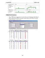
THEN/ELSE actions can be specified as follows: 

THEN/ELSE Actions  Operators 

Remark 

Counter 

RESET 

Counter-x represents the number of the 

Event Counter 

channel 

DO 

ON, OFF 

DO-[X]

 represents the number of the channel. 

Pulse Output 

STOP, START 

Pulse Output-[X]

 represents the number of the channel    

AO 


For ioLogik E1241 expansion 

Relay Output 

RESET 

ResetCNT-[X]

 represents the number of the relay channel. 

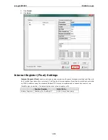
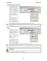
Internal Register 


Reg-x represents the number of the internal register.  
x = 00 to 23 / Trigger Value: 0 to 255 

Timer 

STOP, START, 
RESTART 

Timer-x, x = 00 to 23 
Max value: 4,294,967,295 seconds 

SNMP Trap 


I/O Status Bindings: 3 sets 

Active Message 

ID / Source IP  Unicode supported 

e-Mail 


Create the contents of the email 

Short Message Service   

Select recipients from the phone book, define the content, and 
configure the escalation 

Data Log Start/Stop 

Start, Stop 

Select which profile to start or stop 

FTP Service 


Select which profile and FTP server to upload the log file 


NOTE 

The following THEN Actions are only supported by the ioLogik W5300: 

Short Message Service

Data Log 

Start/Stop

, and 

FTP Service


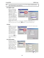
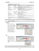
Counter 

In this THEN/ELSE action, the 
only operator for the 

Counter 

function is “RESET”, which clears 
the counts of an Event Counter 
channel. This function is often 
used in a charging system to 
clear the readings of a meter. 
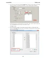
Select the THEN/ELSE action to 

Counter 

and click on the 

property button (

) to enter 

the Counter Settings window. 


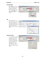
DO 

DO 

refers to the action of 

controlling the local digital 
output channels that react to 
the IF conditions. Select the 
THEN/ELSE action to DO and 
click on the property button 
(

) to enter the DO Settings 

window. 


NOTE 

A Relay output channel is also referred to as a DO channel in the THEN/ELSE action fields. 


Summary of Contents for ioLogik W5300 Series

Page 1: ...ioLogik W5300 Series User s Manual Ninth Edition April 2014 www moxa com product 2014 Moxa Inc All rights reserved ...

Page 2: ...o this manual or to the products and or the programs described in this manual at any time Information provided in this manual is intended to be accurate and reliable However Moxa assumes no responsibility for its use or for any infringements on the rights of third parties that may result from its use This product might include unintentional technical or typographical errors Changes are periodicall...

Page 3: ...1 Import Export a Configuration File 2 12 Using ioAdmin to Import Export a Device Configuration 2 12 3 The ioAdmin Utility 3 1 System Requirements 3 2 Key Features 3 2 Using the ioAdmin Utility 3 3 The ioAdmin Utility Window 3 3 ioAdmin Menu Bar 3 3 The Wiring Guide 3 6 ioAdmin Quick Link Buttons 3 7 ioAdmin Navigation Panel 3 7 Main Window 3 9 Synchronization Rate Status Bar 3 10 ioAdmin Status B...

Page 4: ...ple Data Monitoring from a Remote Site 5 4 Expanding Input Output Channels 5 6 Using Modbus TCP Protocol with Your Program 5 8 Using the Counter to Get Meter Readings and Statistics 5 10 Record your I O Data in the Data Log File 5 11 Connecting a Modbus RTU Serial Device Attached to the ioLogik over a Cellular Network 5 18 Connecting to a SCADA System 5 18 Updating Serial Tags to SCADA System with...

Page 5: ...tion 8 C 18 ioLogik W5312 Modbus Mapping C 19 0xxxx Read Write Coils supports functions 1 5 15 C 19 1xxxx Read only Coils supports function 2 C 24 3xxxx Read only Registers supports function 4 C 24 4xxxx Read Write Registers supports functions 3 6 16 C 26 5xxxx Write Registers supports function 8 C 38 D SNMP Agents with MIB II RS 232 like Groups D 1 E Factory Default Settings E 1 F Troubleshooting...

Page 6: ...ried over cellular communications typically have with dynamic IP addresses NOTE Throughout this user s manual we use ioLogik W5300 to refer to one of any of the product models in the ioLogik W5300 series The following topics are covered in this chapter Architecture Using Active OPC Server to Resolve Dynamic IP Addresses Resolving Dynamic Private IP Issues with DDNS Overview Product Features Appear...

Page 7: ... to actively push communications to the central HMI SCADA system empowering the network with real time I O updates while substantially cutting network overhead Unlike the requirements of a traditional OPC server where remote I O devices must use a static IP so they may be successfully polled Active OPC Server and ioLogik products allow engineers the flexibility of configuring edge devices with dyn...

Page 8: ... need to do is select the channels to be updated from the Active OPC Server Generally speaking tag generation is 50 times faster on Active OPC Server compared to a traditional OPC server making extra training for installation and configuration of the OPC no longer a requirement The traditional polling architecture occupies more network bandwidth which results in longer response times In comparison...

Page 9: ...omized control systems The ioLogik W5300 is a rugged device with tolerance for a wide range of temperatures well suited for hard to wire remote monitoring and alarm applications such at unmanned sites like riversides and pipelines Product Features Trouble free connections to cellular networks Automatic data update from SD cards following network failure Front end intelligence for event handling In...

Page 10: ... Green Cellular modular sending receiving serial TX RX command signal System Fault Status RED I O out of work FAULT OFF Function Normal Blinking Safe Mode Signal Status OFF No signal or No SIM Card SIGNAL 1 Green LED Weak or insufficient SMS only 2 Green LEDs Average good for cellular connections 3 Green LEDs Excellent Signal Physical Dimensions unit mm Package Checklist The ioLogik W5300 is shipp...

Page 11: ... Specifications Computer CPU ARM9 based CPU 32 bit 160 MHz SDRAM Flash ioLogik W5312 4 MB ioLogik W5340 2 MB Storage Expansion Slot Up to 32 GB SD memory card SD 2 0 compatible Note For units operating in extreme temperatures industrial grade wide temperature SD cards are required Cellular Network ioLogik W5312 W5340 Quad band GSM GPRS EDGE 850 900 1800 1900 MHz ioLogik W5340 HSPA Five band UMTS H...

Page 12: ...EN 55022 EN 61000 3 2 EN 61000 3 3 FCC Part 15 Subpart B Class A EMS EN 55024 EN 61000 4 2 EN 61000 4 3 EN 61000 4 4 EN 61000 4 5 EN 61000 4 6 EN 61000 4 8 EN 61000 4 11 EN 61000 6 2 Shock IEC 60068 2 27 Freefall IEC 60068 2 32 Vibration IEC 60068 2 6 Green Product RoHS CRoHS WEEE Note Please check Moxa s website for the most up to date certification status Warranty Warranty Period ioLogik W5312 5...

Page 13: ...re Time 407 406 hrs Database Telcordia Bellcore ioLogik W5340 W5340 T W5340 HSPA W5340 HSPA T Inputs and Outputs Analog Inputs 4 channels Configurable DIOs 8 channels Relay Outputs 2 channels Isolation 3K VDC or 2K Vrms Analog Input Type Differential input Resolution 16 bits I O Mode Voltage Current Input Range 0 to 10 V 10 V 5 V 0 to 20 mA 4 to 20 mA Accuracy 0 1 FSR 25 C 0 3 FSR 30 and 70 C Samp...

Page 14: ...elay Output Type Form A N O power relay Contact Current Rating Resistive Load 1 A 30 VDC 250 VAC 110 VAC Initial Insulation Resistance 1000 m ohms min 500 VDC Mechanical endurance 5 000 000 operations Electrical endurance 600 000 operations 1 A resistive load Contact Resistance 100 m ohms max Pulse Output 0 3 Hz at rated load Power Requirements Power Consumption ioLogik W5340 Always on 195 mA 24 V...

Page 15: ...ecting to ioAdmin via Ethernet Configuring the Computer s IP Address Activating ioAdmin and connecting to the ioLogik Configuring Digital I O Channels Connecting I O Devices Testing I O Devices DIN Rail Wall Mounting Installing Removing SIM and SD Cards Connecting the ioLogik W5300 to a Cellular Network Installing AOPC on a Host with a Static IP Address Import Export a Configuration File Using ioA...

Page 16: ... Insert the Document and Software CD into the host computer In the Software Utility directory of the CD locate and run SETUP EXE The installation program will guide you through the installation process and install the ioAdmin utility After the installation is finished run ioAdmin from the Windows Start menu You can also download ioAdmin from Moxa s website Navigate to the moxa website at http www ...

Page 17: ...e current for each power wire and common wire Observe all electrical codes dictating the maximum current allowable for each wire size If the current exceeds the maximum rating the wiring could overheat causing serious damage to your equipment For safety reasons we recommend an average cable size of 22 AWG However depending on the current load you may want to adjust your cable size the maximum wire...

Page 18: ... may also click System on the menu bar then select Auto Scan ioLogik device A dialog will appear Click Start Search Once the ioLogik has been detected modify the settings as needed for your network environment and then restart the device NOTE The best approach to setting up a previously configured ioLogik is to first reset it to the factory default using the reset button see Chapter 1 for details ...

Page 19: ...to check if the setting has been successful by refreshing the list of units found by ioAdmin 4 Login as administrator For full access to all configuration options log in as administrator from the Server Settings panel This is required whenever you start ioAdmin or boot up or restart the ioLogik When you install the ioLogik for the first time the password will be blank and you can simply click Logi...

Page 20: ...se ioAdmin to set up or configure your unit Refer to Chapter 3 for additional information on using ioAdmin Configuring Digital I O Channels The ioLogik W5300 product family is equipped with different I O types including analog inputs digital inputs digital outputs relay outputs and software configurable DIOs offering great flexibility for connecting I O devices such as software configurable DIO ch...

Page 21: ...tact PNP and NPN sensors at the same time The sensor type determines your wiring approach as shown in the following examples this example shows the pin numbers for an ioLogik W5340 unit Analog Input Digital Input Dry Contact Digital Input Wet Contact Connect to NPN type Sensor Digital Input Wet Contact Connect to PNP type Sensor Digital Output Sink Type ...

Page 22: ...3 forming one group and DIO 4 to DIO 7 forming another group If an NPN sensor is connected to DI 0 then only NPN sensors can be connected to the other DI channels in that group i e DIO 1 DIO 2 and DIO 3 Likewise if a PNP sensor is connected to DIO 4 then only PNP sensors can be connected to the other DI channels in that group i e DIO 5 DIO 6 and DIO 7 Testing I O Devices Power on the ioLogik W5300...

Page 23: ...remove or install a SIM or SD card 1 Remove the screw holding the card cover in place 2 There are two different card slot types used on the ioLogik series of devices a On ioLogik W5312 and W5340 models directly insert or remove the SIM SD card into the respective slot b On the ioLogik W5340 HSPA you must first depress the card locking mechanism to eject the card Use a pointed instrument like a bal...

Page 24: ...When the environment is ready follow these steps to test the ioLogik W5300 refer to the figure below Step 1 Connect directly from the PC to the W5300 and use ioAdmin to configure the W5300 s cellular settings Step 2 For the ioLogik W5300 enter the user name password SIM Pin APN and define the Active OPC server IP on the cellular settings page Make sure the Operation Mode is correctly selected Step...

Page 25: ...g AOPC on a Host with a Static IP Address Moxa s Active OPC Server is an OPC software driver for an HMI or SCADA system It seamlessly connects Moxa s ioLogik products to a wide variety of SCADA systems including the most popular Wonderware Citect and iFix Active OPC Server conforms to the OPC Foundation s DA 3 0 data access standard Active OPC server must use public static IP address 1 To install ...

Page 26: ...on ATTENTION Since there are major functional differences between firmware versions exporting the configuration file requires a longer processing time Adjust the TCP Socket Timeout Interval to 30 seconds when using ioAdmin 3 10 or above especially if earlier versions of ioAdmin have been installed and then removed Import System Config Select this command to load a configuration for the selected io...

Page 27: ...n Panels The Server Settings Panel The LAN Settings Panel The I O Configuration Panel Configuring AI Channels Configuring Digital I O Channels Configuring Digital Input Channels Configuring Digital Output Relay Output Channels Testing DI and DO Channels The I O Expansion Panel I O Expansion Step by Step The Active Tags Panel Active OPC Redundancy Mode The Cellular Settings Panel Dial up Setting Ca...

Page 28: ... Key Features Remote Management Over the Ethernet or Cellular network ioAdmin allows users to Search and configure multiple ioLogiks Perform I O status monitoring and control Use active message monitoring Use Click Go local logic control configuration Use the firmware upgrade interface Restart the ioLogik Reset to factory defaults On line Wiring Guide A wiring guide can be opened from within ioAdm...

Page 29: ...istrator 1 Window title 3 Quick link buttons 5 Main window 7 Status bar 2 Menu bar 4 Navigation panel 6 Sync rate status ioAdmin Menu Bar Menu Bar File Here you can save import or export a configuration file or lists of servers and devices When importing or exporting device lists you will be prompted for source and destination devices with a popup window You may click on the Folder icon to select ...

Page 30: ...xes or by using a netmask with a starting IP address Model Search for selected models click all that you are interested in finding Click Start Search to begin Whenever a device is found it will display in the lower portion of the window Network Interface If the PC has multiple network adapters installed this allows you to select which NIC the device will connect over The default network interface ...

Page 31: ... Port Setting is used to set the default serial communications parameters so the ioAdmin utility may establish a Modbus connection The fields are baud rate data bits stop bits parity and timeout interval For most applications this will involve connecting to ioLogik R series devices Active Message Listen Port specifies the port number over which the ioLogik will listen for Active Messages If the ac...

Page 32: ...y be set in the Server Settings Panel or whether or not the device suports an Active OPC client The Wiring Guide ioAdmin provides a wiring guide for the ioLogik W5300 series You can access the wiring guide by right clicking the ioLogik figure in the I O Configuration panel or by clicking on the Wiring Guide icon in the submenuat the top of the windo The wiring guide is a help file showing wiring i...

Page 33: ...d explained in the table below ICON Navigation Panel View Sort according to the connection using subnets and IP addresses Sort according to device type using the ioLogik model number Sort by the ioLogik s location field this is a descriptor that is defined in the ioAdmin s Server Settings Panel Show all devices that support an Active OPC client NOTE The default location is Empty If you have not se...

Page 34: ... the device list shown in the navigation panel the target must first be disconnected from the network Once deleted a device must be reconnected to the network using the ioAdmin search process described above Restart System Select this command to restart a selected ioLogik RTU Reset to Default Select this command to reset all settings on the selected ioLogik including the password and all configura...

Page 35: ...General The I O Configuration panel shows the status of every I O channel This is the default panel when you first open ioAdmin Input channels are listed on the left and output channels are listed on the right For more information about configuring I O see the section I O Configuration Panel below Server Info Panel Information such as the device name configured IP address and firmware version is d...

Page 36: ...n defined and activated any TCP UDP messages that have been triggered by sensor events will be shown on the monitor Messages can be displayed in ASCII HEX or 2 byte Unicode UCS2 To select your preferred code check the appropriate button at the bottom of the window Unicode supports multiple languages Synchronization Rate Status Bar The current sync rate is displayed on the bar at the bottom of the ...

Page 37: ...n order to take effect ATTENTION You MUST log in as administrator to access the Network Watchdog Timer and Firmware Update panels If you forget the password hold down the reset button to clear the password and load factory defaults This will result in the loss of all configuration settings and any Click Go logic that may have already been configured The Server Settings Panel In the Server Settings...

Page 38: ...pond due to a hardware failure or a network problem the ioLogik will continue to wait for a response from the host This will cause the TCP port to be occupied indefinitely by the host On the other hand if an idle connection timeout interval is enabled for Modbus TCP then when the ioLogik s connection to the server exceeds a specified time period the device will automatically release its modbus TCP...

Page 39: ...roduct picture Horizontal View includes the product picture whereas Vertical View does not show the product picture Configuring AI Channels The ioLogik W5340 and W5340 HSPA are both equipped with 4 AI analog input channels that can be set individually to 5 V 10 V 0 to 10 V 0 to 20 mA and 4 to 20 mA You may also set all channels at once using the Apply to all channels check box left figure below Al...

Page 40: ...w higher temperature values You may then cut off any values beyond 17 mA and convert those to a proprietary danger level such as Level 5 Auto Scaling with the slope intercept formula provides linear conversion with one ratio M and offset D Offset can be an initial value of field device Ratio can help enlarge or reduce the scale by specifying a proportion It is also easy to modify the values in the...

Page 41: ...nel s scaling function so that 1 tick of counter input equals 5 ml Next we set the Accumulation flag and configure the Time Interval to 24 hours This will set up the virtual channel to log the total water flow volume over a period of 24 hours NOTE Virtual channels are required to configure AI or counter channels For counter channels configure the Counter Scaling on the I O Configuration panel befo...

Page 42: ... accepts values between 1 and 65535 For example a setting of 100 would mean a 50 ms filter 100 0 5 ms The Mode dropdown may also be used to set the channel as straight Input DI or as an Event Counter Type On Off Dry contact Short to GND Open Wet contact 0 to 3 VDC 10 to 30 VDC When set as an Event Counter the channel will accept limit or proximity switches and will tabulate ON OFF signal events Wh...

Page 43: ...or a Click Go command You can also specify counting to begin automatically whenever the ioLogik is powered on To configure automatic counting select Start under Counter mode parameter in the Power On Settings which is located under the DI Config tab within the DI Channel Window You can configure how a counter behaves during a network disconnect by navigating to the Watchdog panel click on the Watc...

Page 44: ...will generate a square wave as specified in the pulse mode parameters The low and high level widths are specified in multiples of 0 5 ms for Digital Output 1 5 s for Relay output with a maximum setting of 65 535 For digital output you would enter 1000 for a width of 500 ms If the OFF width value is 5000 and the ON width value is 5000 the pulse output would be a square wave with a 5 second pulse cy...

Page 45: ...trol how a digital output relay output channel acts when the network is disconnected by navigating to the Watchdog tab in the main window panel and setting the appropriate parameters in the Safe Status Settings and the Host Connection Watchdog panels When the Host Connection Watchdog is enabled a network disconnection will activate a safe state The DO channel can be configured to turn on turn off ...

Page 46: ...of expansion modules allowed is three E1200 expansion units do not need to be directly connected e g they may be connected using a switch but they must be installed on the same network segment as the ioLogik W5300 or they will not be detected To configure an E1200 expansion unit for use with the ioLogik W5300 follow these steps 1 Start ioSearch and use it to detect your ioLogik E1200 external expa...

Page 47: ...s using the following firmware versions W5312 V1 3 and above W5340 V1 6 and above W5340 HSPA V1 3 and above W5340 models with firmware v1 5 can support these 5 models E1210 E1211 E1212 E1214 and E1240 I O Expansion Step by Step Step 1 Use ioSearch to configure the signal parameters for each ioLogik E1200 I O channels First configure the E1200 device for connection to the network For details on how...

Page 48: ...iguration files into the w5300 s ioAdmin utility restart the ioLogik W5300 Open ioAdmin and log in The ioLogik W5300 and expansion modules will be shown on the screen with the IP address of a device listed above the device When you add an I O expansion module such as the ioLogik E1210 or E1211 additional tabs will appear as shown below Step 5 Use ioAdmin to configue the higher order logic for the ...

Page 49: ...val configures the period of time for the heartbeat signal to the AOPC server this is used to confirm the connection between an ioLogik device and the Active OPC server is live If the heartbeat interval is set and the network between the ioLogik and Active OPC server is down the AOPC panel will detect the heartbeat has stopped and will display BAD in the Quality column to indicate the loss of conn...

Page 50: ...eartbeat signal can be used to verify for the AOPC server that the ioLogik device remains active over a live connection If a heartbeat is configured and the connection between the ioLogik and AOPC server is broken the AOPC server will detect that the heartbeat has stopped and then display in the Quality column the BAD label to indicate the device is down The ioLogik W5300 heartbeat is especially u...

Page 51: ...represent the percentage of the full analog range For example if the AI is configured for 0 to 10 V on change 1 means the ioLogik will update the Active OPC Server every time there is a change of 0 1 V 3 Expansion modules added to the system are displayed in the modules list Select a module to see detailed tags in the right panel of the browser window After selecting the needed tags click the Crea...

Page 52: ...oid this problem the ioLogik W5300 will try to connect to the cellular network one time only If it fails then the W5300 will stop trying to connect to the cellular network You can leave the username password and SIM PIN fields blank for most cases because they are seldom used After all information has been configured correctly click Update The ioLogik W5300 must reboot in order for the settings to...

Page 53: ...Cellular Backup The ioLogik W5300 may also be configured with redundant network interfaces so that it uses cellular networks only as a backup connection When this mode is selected the primary interface will be the Ethernet connection over the Internet Should this primary interface fail the ioLogik W5300 will automatically switch to the cellular interface and then switch back to the primary Etherne...

Page 54: ...hentication NOTE Currently the ioLogik W5300 supports DNS service as provided by DynDNS For detailed information on this option please visit https www dyndns com Port Forwarding The ioLogik W5300 supports port forwarding on its cellular and Ethernet interfaces for WAN to LAN communication Using port forwarding the ioLogik W5300 allows external WAN hosts such as SCADA HMI systems to connect to spec...

Page 55: ...ation protocolfor IP packets In the example below an encrypted VPN connection is established with a remote VPN server ioLogik connects to the server in tunnel mode using the IPsec protocol suite The following encryption ciphers and AAA protocols are available using this setup Manual Key ESP IKE PSK DES 3DES AES128 AES192 AES256 encryption MD5 SHA1 authentication IPsec NAT traversal Anti Replay and...

Page 56: ...Enter the ioLogik W5300 HSPA subnet LAN IP Local Subnet netmask Enter the ioLogik W5300 HSPA subnet netmask Manual Key ESP SPI Sets the VPN manual key incoming outgoing SPI between 257 and 4294967295 Encryption mode Selects the incoming outgoing encryption mode Encryption key Enters the incoming outgoing encryption key Encryption mode Length Bytes DES 8 3DES 24 AES 128bit 16 AES 192bit 24 AES 256b...

Page 57: ... NAT traversal NAT T Enabling this option will allow IPsec traffic from this endpoint to traverse through the translation process during NAT The remote VPN endpoint must also support this feature and it must be enabled to function properly over the VPN default disable Encryption mode Select the VPN ISAKMP phase 1 encryption mode Authentication mode Select the VPN ISAKMP phase 1 authentication mode...

Page 58: ... VPN will continuously re establish a connection default Disable VPN System Log Events and Error Codes VPN system log Description UNLINK_TIME_REACH SA Lifetime timeout UNLINK_TIME_OUT No response from remote VPN server UNLINK_NO_PROPASOL The remote VPN server does not have matched VPN settings proposal UNLINK_DPD DPD detecting IKE_PHASE1_MAIN_START IKE phase1 Main mode starts IKE_PHASE1_AGGR_START...

Page 59: ...aches the timeout it will perform a system restart GSM Timeout When you turn on the ioLogik W5300 the device will continue to connect to the GSM for a period of 60 seconds the default setting If it fails to connect the device will automatically restart the modem board after sixty seconds GPRS Retry After the connection between the device and GSM carrier has been made The device will try to connect...

Page 60: ... from 1 to 24 hours Meter Sensor OP Mode The ioLogik W5300 supports four OP modes Transparent Serial Tunnel TCP Server and TCP Client Modbus TCP Modbus RTU Gateway and Modbus Serial Tags Transparent Serial Tunnel Transparent Serial Tunnel mode creates a TCP socket to a remote host program and transparently sends and receives data to attached legacy serial devices Modbus RTU Gateway This function a...

Page 61: ...e Active OPC server active message server serial TCP SNMP trap Email FTP Modbus DA Center Event Log and ICMP The Network Statistics Page will help you understand the overall usage of the network Watchdog Panel The Watchdog panel is available after you log in as administrator When enabled the Host Connection Watchdog monitors the network connection If the connection is lost for the specified Timeou...

Page 62: ... soon as user defined I O conditions have been met Refer to Chapter 4 for more detailed information on defining rules Changes on the Click Go Logic panel are not effective until the ioLogik W5300 is restarted as is true with changes made on other panels After logging back in as administrator and returning to the Click Go Logic panel click Download to view the current ruleset Click Run to activate ...

Page 63: ...nfigurable DIO Channel Mode Selection Digital Input Mode Selection Digital Output Mode Selection Analog Input Mode Selection Alias Configuration Testing the I O Channels Defining Global Variables Internal Register Integer Settings Timer Settings SNMP Trap Server E Mail Server Active Message Server SMS Phone Book Working Off Working Days FTP Settings Data Logging Profile List Internal Register Floa...

Page 64: ... UDP message only when the switch attached to DI 0 is turned on This event based structure results in a much improved response time and a much reduced load on the host computer s CPU and network bandwidth The ioLogik W5300 supports Moxa s Click Go Logic With Click Go Logic you can easily and intuitively configure when and how I O information is transmitted over the network Simple IF Then Else stat...

Page 65: ...ble interval for time triggered events NOTE In this chapter all the descriptions are based on the ioAdmin 3 10 Be sure to use firmware V1 3 or above for the ioLogik W5312 series firmware V1 5 or above for the ioLogik W5340 series and Active OPC Server V1 11 or above Click Go Logic Basics To use Click Go Logic start ioAdmin and log on as an ioLogik administrator on the Server Settings panel Once yo...

Page 66: ...you must select the unit of measurement before entering a value If you select a unit of measurement after entering a value the value will not be retained In addition when an I O channel is being used in a Click Go Logic rule the channel s range and units cannot be modified Click Go Development Process After searching and setting up the IP address of an ioLogik Ethernet I O server Click Go logic ca...

Page 67: ...Mode Selection A DI channel can be set to DI or Event Counter mode In DI mode the channel connects to wet dry contacts In Event Counter mode the channel accepts limit or proximity switches and counts events according to the ON OFF status When Lo to Hi is selected the counter value increases when the attached switch is pushed When Hi to Lo is selected the counter value increases when the switch is ...

Page 68: ...ll be configured to act as either a DO or Pulse Output channel according to the Mode Settings To switch between DO and Pulse Output channel operation select the desired mode under Mode Settings Analog Input Mode Selection Analog input channels can use either voltage or current to transmit signals Model Number of Analog Input Channels Mode Selection Voltage Current ioLogik W5340 HSPA ioLogik W5340 ...

Page 69: ...th configuration options for that channel The Alias name of each input output channel can be configured by selecting the Alias Name panel ATTENTION We strongly recommend configuring the alias name for the I O channel being used before performing any further configuration or programming Testing the I O Channels Each I O channel can be tested and monitored individually When logged in as administrato...

Page 70: ... registers can be polled and controlled by SCADA software using standard Modbus TCP format or implemented to redirect the result of one Click Go logic to another The default value of an internal register is 0 Register Number Initial Value Internal Register Reg 0 to Reg 23 0 to 255 Timer Settings The Timer function allows users to delay an action trigger an action to run or repeat an action A timer...

Page 71: ...il addresses The Recipient Database should contain a list of available e mail addresses for your network environment The e mail message defined in the Click Go logic will be sent to all addresses listed in the Receiver s list To add e mail addresses to the Available receiver s list enter the Name and Mail Address and click the Add finger icon to move addresses to the Recipient Database use the Rem...

Page 72: ...he Click Go logic will be sent to all addresses listed in the Message Recipient List Message Port TCP UDP The Port the computer uses to communicate with the device the default port for TCP UDP is 9000 SMS Phone Book The SMS Phone Book configures one or more destination phone numbers that will receive SMS Short Message Servers event messages generated by the Click Go logic The SMS defined in the Cl...

Page 73: ...k days and hours first double click to select the date in the calendar and then click the Replace button to update the selected entry of the off days FTP Settings The FTP Settings dialog defines the target FTP server s IP and user accounts to allow the ioLogik W5300 to upload log files Specify the FTP Server s IP address and accounts and press the Add button to create a new entry in the list ...

Page 74: ...included in different profiles Take the following steps to create a profile 1 Click the New button to create a new profile 2 Click Enable and specify a name for the profile In addition specify the Initial State and capacity of a log file If you select Start as the initial state logging will start immediately once the profile is established If you select Stop a Click Go logic must be performed to s...

Page 75: ...ule The Schedule settings are extremely flexible and can log by day week or month Specify the hours and then click the Add button to add a setting of the schedule to the list Click Next to proceed 4 Specify the channels to be logged The percentage indicates the change of an analog channel when choosing the On Change logging type Specify the percentage for an analog channel before selecting the cha...

Page 76: ...g with the Click Go logic internally or externally The 28 sets of internal registers float can be polled and controlled by SCADA software using the standard Modbus TCP format or implemented to redirect the result of one Click Go logic to another The default value of an internal register is 0 Register Number Initial Value Internal Register FloatReg 0 to FloatReg 27 0 000 4 byte float point ...

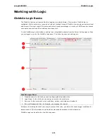
Page 77: ...ioLogik administrator from the Server Settings panel Once you are logged in go to the Click Go Logic panel The following screen should appear Click Go Logic Panel 1 Global Variable In this field you can configure global variable rules 2 Logic Name In this field you can assign a name to the set of rules 3 Rule set In this area each rule s conditions actions and status are displayed 4 Rule set Manag...

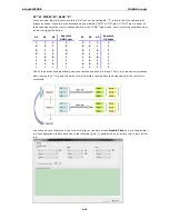
Page 78: ...D Logic A1 A2 A3 Result of OR Logic 0 0 0 0 0 0 0 0 0 0 1 0 0 0 1 1 0 1 0 0 0 1 0 1 0 1 1 0 0 1 1 1 1 0 0 1 1 0 0 1 1 0 1 1 1 0 1 1 1 1 0 1 0 0 0 1 1 1 1 1 1 1 1 1 The 24 rules are defined individually and are executed one by one in a loop The 2nd rule can only be processed after running the 1st rule and the entire rule set will start running from the beginning after the last rule is processed You...

Page 79: ...when a door is opened Use the pull downs to specify the conditions and units of measurement e g DI 0 OFF IF conditions may be defined as follows IF Conditions Operators Remark DI ON OFF ON to OFF OFF to ON Change DI x represents the channel number Counter Change Counter x represents the channel number Max Counter Value 4 294 967 295 AI AI x represents the number of the channel Max Value Depends on...

Page 80: ...r ON to OFF and OFF to ON transitions Scroll to select DI and click on the property button to enter the DI Settings window Counter Counter refers to the counts of an Event Counter channel The counts are stored in the ioLogik internally Specifying the counts with a proper operator will lead to triggering the action For example if 10 items should be packed in a box the Counter x should be reset ever...

Page 81: ...ter Integer represents a status flag to link the status of the first logic to the second one It is used most often with the Timer function or to combine other input statuses together The Internal Register function also allows a PC to control the ioLogik s local output when the remote output is controlled by a Click Go log e g digital output active message e mail or SNMP Trap Select the IF conditio...

Page 82: ...hich helps the user indentify the relationship between rules In addition the Set Timer button will help define the default value for the Timer Schedule The Schedule function allows users to set a starting point or time period for a task For example the Schedule function could be used if a pump needs to start at 9 00 PM and stop at 11 00 PM every Monday Wednesday and Friday Select the IF condition ...

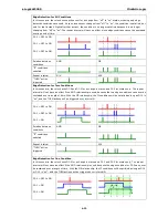
Page 83: ... period of time However if a condition is based on edge detection i e ON to OFF or OFF to ON it can only be triggered once The following scenarios illustrate how edge detection affects the Timer N sec In each diagram the statuses of three sensors are shown over a period of time with a high signal corresponding to a true condition The green shaded area shows the duration of time that the IF conditi...

Page 84: ...r a change in status and DI 2 for status only The repeat interval will not have an effect if the AND relationship is used because the two edge conditions can never be sustained over a length of time With the OR relationship the IF conditions will be satisfied as long as DI 2 is on and the THEN actions will be triggered over interval N DI 0 OFF to ON DI 1 OFF to ON DI 2 ON Relation between conditio...

Page 85: ...ible actions include changing the status of a DO channel starting or stopping an Event Counter or sending a message by SNMP trap TCP UDP or e mail If Conditions Result of AND Logic Trigger of Then Actions Trigger of ELSE Actions A1 A2 A3 0 0 0 0 NO YES 0 0 1 0 NO YES 0 1 0 0 NO YES 0 1 1 0 NO YES 1 0 0 0 NO YES 1 0 1 0 NO YES 1 1 0 0 NO YES 1 1 1 1 YES YES If Conditions Result of OR Logic Trigger ...

Page 86: ...from the phone book define the content and configure the escalation Data Log Start Stop Start Stop Select which profile to start or stop FTP Service Select which profile and FTP server to upload the log file NOTE The following THEN Actions are only supported by the ioLogik W5300 Short Message Service Data Log Start Stop and FTP Service Counter In this THEN ELSE action the only operator for the Cou...

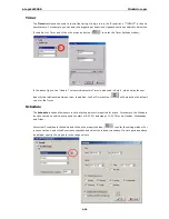
Page 87: ... action of controlling the local Analog Output channels that react to the IF conditions Select the THEN ELSE action to AO and click on the property button to enter the AO Settings window Relay Counts In the THEN ELSE action Relay refers to the current counts specifying how many times a relay has been triggered The counts are stored internally and can be cleared RESET is the only operator Select th...

Page 88: ... be controlled by Modbus TCP protocol Refer to the appendix for the address list of all Internal Registers Timer The Timer function can be used to control the time settings of a logic rule Actions such as START STOP and RESTART can be configured here Select the IF condition for Timer and click on the property button to enter the Timer Settings window In the above figure the Used in column indicate...

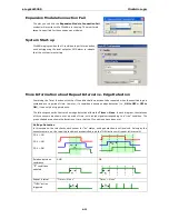
Page 89: ...ndow Enter your desired message in the Message Content column Dynamic fields such as time date IP address and I O status can be inserted in your message by clicking Keyword Lookup Messages are sent in ASCII by default but can be sent in HEX by selecting the Send as HEX separated by checkbox Click the Set Active Message button to configure the default parameters such as the messaging protocol TCP o...

Page 90: ...of the messages will be the same If you would like to send an Active Message and e mail based on the same event but with different content you will need to use two separate logic entries one for the Active Message and one for the e mail SMTP server information including username password and the recipient database can be configured by clicking the Set Mail Address button Click the finger icon to m...

Page 91: ...e listed in the recipient list and using the timeout interval A recipient will stop receiving the SMS alarm when the preset maximum repeat times is reached or when one receiver acknowledges receiving the SMS NOTE Send every means to send the SMS to all the recipients SMS Escalation will send SMS to the recipients sequentially and wait for the response acknowledgement Data Log Start Stop The Data L...

Page 92: ... ioLogik will upload the entire Log_01 Log_02 and Current Log_03 In the Next 24 hrs the ioLogik will upload the entire Log_03 Log_04 and Current Log_05 On the FTP Server the Current Log_03 will be overwritten by the entire Log_03 when an additional 24 hrs has passed Activating the Rule set Upload Restart and Run The rules that are displayed on the Click Go Logic panel include the current rule set ...

Page 93: ...PC independent automation Clear Erases the rule set in both ioAdmin and the ioLogik W5300 series Retrieve Copies the rule set from the ioLogik W5300 into ioAdmin Upload to ioLogik Copies the rule set from ioAdmin to the ioLogik W5300 Run Activates the rule set that the ioLogik booted up with Stop De activates the Click Go rule set and returns the ioLogik to normal passive operation Import Export C...

Page 94: ... Remote Site Expanding Input Output Channels Using Modbus TCP Protocol with Your Program Using Counter to Get Meter Readings and Statistics Record your I O Data in the Data Log File Connecting a Modbus RTU Serial Device Attached to the ioLogik over a Cellular Network Connecting to a SCADA System Updating Serial Tags to SCADA System with Active OPC Server over a Cellular Network Handling Front End ...

Page 95: ...ystem is now able to leverage this technology by connecting the Active OPC Server using Modbus TCP or OPC Client Drivers instead of connecting to the remote ioLogik s IP address directly Known Issue 2 Low Bandwidth and slow response time Cellular networks provide only low bandwidth transmission compared with wired CAT 5 Ethernet networks Generally speaking the response time of the GPRS network is ...

Page 96: ...me services provided by a VPN 2 Network with Public Static IP Devices A Public Static IP can be accessed anywhere and anytime such as over the Internet Although most carriers use private dynamic IPs for mobile phones some carriers will provide Public Static IPs for specific applications The downside of Public Static IP service is that it comes at a much higher price Some telecom service providers ...

Page 97: ...ADA system through an OPC client server or Modbus TCP You can push datalog files to the FTP server and connect field serial devices through a serial tunnel In addition the ioLogik W5300 supports event alarms by email SNMP Trap and SMS In the following sections we illustrate how to set up an environment for the ioLogik W5300 Using ioAdmin to Perform Simple Data Monitoring from a Remote Site Scenari...

Page 98: ...address on the Active Tags panel as the Active OPC Server address Step 6 Install the AOPC Server on a PC with a static IP address and ensure the IP address of the AOPC server is available and accessible from the remote ioLogik Step 7 Before starting the Active OPC server make sure that any local routers or firewalls which it is running behind are configured to forward TCP ports 9900 9500 9300 and ...

Page 99: ...ing the ioLogik E1210 and E1211 to add an additional 16 DIs and 16 DOs Implementation Step 1 Connect to the ioLogik E1210 and E1211 and start the Web Consoles for these two products Step 2 Configure and export the configuration files of these two models The file names will be ik1210 txt and ik1211 txt Step 3 Use Ethernet cables to daisy chain the W5340 E1210 and E1211 and connect to the host PC th...

Page 100: ...tep 9 After rebooting log in to ioAdmin as Administrator and choose I O Configuration You will see the following screen which indicates that the additional I O channels were successfully installed Step 10 Click Go will continue running when the connection between the ioLogik W5300 and expansion modules is down You can use the trigger condition Expansion module connection fail to let Click Go warn ...

Page 101: ...nformation from different remote sites The most common way of doing this is to use Modbus TCP The following example illustrates the procedure Environment 1 Active OPC server Public Static IP 59 124 42 169 Internal Static IP 192 168 19 19 2 Central site Internal Static IP 59 124 42 169 3 W5300 IP 116 59 60 232 a public IP is required Diagram We use ModScan32 to illustrate ModScan32 is a product of ...

Page 102: ... next step NOTE Some service providers carriers forbid and will filter this actiion Step 7 Click on the ModScan32 icon to open ModScan32 as shown below Step 8 Click Connection on the toolbar and choose Remote TCP IP server in the Connect Using column Input the W5300 s IP address in the IP Address column and then click OK Step 9 Choose New from the File menu ...

Page 103: ... to Get Meter Readings and Statistics Scenario In water pipeline monitoring applications water flow volume is a very important monitoring factor since it can be used as an indication of leaking The sensor used to monitor water flow volume is called a flow meter Most flow meters have a pulse output of 4 to 20 mA signal output which the user needs to convert to water flow in their own PC software In...

Page 104: ... the value on the I O configuration Panel The virtual channel value can be updated to AOPC with the Active Tags function Record your I O Data in the Data Log File Scenario A cellular communication system has lost its connection unexpectedly If the user stores data in a PC database the database may lose data when the cellular network is disconnected For this reason the ioLogik W5300 provides a fron...

Page 105: ...k W5300 Planning and Assistance 5 12 Step 4 Click the New button to create a new log profile Step 5 In the new profile click Enable to activate the profile specify the settings and then click Next to proceed ...

Page 106: ...ioLogik W5300 Planning and Assistance 5 13 ...

Page 107: ...ce 5 14 Step 6 Select the channels that needed to be logged and then click the Finish button Step 7 Click the Save button If you select Start for the initial state in Step 5 data logging will start immediately when the profile is created ...

Page 108: ...Global Variables toolbar Step 2 Specify the FTP server address and account and then click Add Step 3 Double click on the Click Go rule entry Step 4 In the IF Condition select Schedule and then configure its properties to upload every midnight 00 00 to 00 15 NOTE The Timer function can also be used for other applications ...

Page 109: ...ioLogik W5300 Planning and Assistance 5 16 Step 5 In the THEN Action select FTP Service and specify which profile s log files will be uploaded ...

Page 110: ... Yes to restart the ioLogik system Step 7 On the Click Go panel click Run to activate the logic The Log file will be uploaded based on the current settings NOTE The function is dependent on the firmware version Be sure to use firmware V1 3 or above for the ioLogik W5312 series and firmware V1 5 or above for the ioLogik W5340 series ...

Page 111: ...e field serial device via the serial port making sure that the signal wiring is correct Step 6 By specifying the W5340 s IP address and the ID of the attached serial devices you can use the Modbus TCP master to query the remote serial device NOTE The Modbus Slave ID for the ioLogik W5300 is fixed at 1 which means that the ID of the Modbus RTU meters attached to the ioLogik should start from 2 to 2...

Page 112: ...Select 4 AIs for update tags and then click the Create Tags button Step 5 ioAdmin will prompt you to restart the device Step 6 Open Active OPC server You will see the device and data for 4 AIs in the display window Step 7 Connect to the SCADA system and choose the OPC server as Moxa Active OPC Server Step 8 Follow SCADA instruments to create data tags for these 4 analog inputs Step 9 After creatin...

Page 113: ...ports attaching field serial Modbus RTU meters either RS 232 or RS 485 and allows the integration of this serial data so that it can be uploaded to the SCADA system via the Moxa Active OPC Server software Setup Procedure Step 1 Start ioAdmin as administrator Step 2 Choose the Meter Sensor tab Step 3 Set the serial port parameters RS 232 RS 485 Baudrate Stop Bits etc Step 4 Click Modbus Serial Tags...

Page 114: ...mware V1 3 or above for the ioLogik W5312 series and firmware V1 5 or above for the ioLogik W5340 series Handling Front End Events and Alarms Scenario This application uses many unmanned sites and the customer would like to receive an alarm if the monitored status changes We assume that the water level of the water tank is measured with DI 1 The DI 1 starts as OFF which indicates a normal water le...

Page 115: ...fter rebooting click Run The logic will go live Once the water level is detected by a sensor your mobile phone will receive the SMS NOTE 1 The above procedure can be handled over the LAN or from a remote location 2 The E Mail SNMP Trap and TCP UDP alarm can be configured in the same way SMS Escalation and Acknowledgement Scenario In this example we describe how to use the SMS alarm function to con...

Page 116: ... In this example DI Off to On triggers the SMS Step 3 In the THEN settings select Short Message Service and click the Properties button to see detailed settings On the SMS Content panel select the receivers from the phone book Note that multiple receivers can be selected Select SMS Escalation to activate this function ...

Page 117: ...or more SMS commands please refer to Appendix C NOTE When using the SMS related function be sure to get an appropriate data plan from your cellular provider For example a SIM card that only supports data service has the lowest priority to send or receive an SMS In such cases users must activate the voice service on this SIM to ensure faster response for the SMS We strongly recommend checking with ...

Page 118: ... For more SMS commands please refer to Appendix C NOTE Output control via SMS is forbidden if the output channel is currently in use by the Click Go logic Integrate the Internal Register function for output control NOTE When using the SMS related function be sure to get an appropriate data plan from your cellular provider For example a SIM card that only supports data service has the lowest priori...

Page 119: ...d Data Logging functions will continue to work properly Step 3 Checkmark the Wake on Call checkbox Step 4 Input the appropriate phone numbers in the Caller ID column You may input a maximum of 5 phone numbers Step 5 After restarting the system you can use your cell phone to connect the device to the Cellular network Enabling Ethernet and Cellular Redundancy Scenario In this example we describe how...

Page 120: ...URL for the alive check for the Ethernet interface Click Update and restart the ioLogik to activate this function NOTE The Dest IP URL must be specified so the Ethernet port will detect and switch to the backup cellular interface when the primary Ethernet Interface fails ...

Page 121: ...ector CN2 DB9 Male RS 232 Connector CN3 RJ 45 Ethernet Connector TB1 Power Input Terminal Block TB2 I O Terminal Block W5340 TB3 5 pin 4 wire 2 wire RS 422 485 Terminal Block TB2 I O Terminal Block W5312 Cable Wiring Digital Input Dry Contact Digital Input Wet Contact Digital Output Sink Mode Relay Output Analog Input ...

Page 122: ...iring A 2 Pinouts CN1 SMA Cellular Antenna Connector CN2 DB9 Male RS 232 Connector PIN RS 485 Signals 1 DCD 2 RxD 3 TxD 4 DTR 5 Signal GND 6 DSR 7 RTS 8 CTS 9 N C CN3 RJ 45 Ethernet Connector PIN Signals 1 TxD 2 TxD 3 RxD 4 5 6 RxD 7 8 ...

Page 123: ...O 3 VIN1 4 VIN1 5 DI_COM1 6 DIO0 7 DIO1 8 DIO2 9 DIO3 10 GND 11 R0_NO 12 R0_C Terminal Block Right PIN Signals 13 VIN2 14 VIN2 15 VIN3 16 VIN3 17 DI_COM2 18 DIO4 19 DIO5 20 DIO6 21 DIO7 22 GND 23 R1_NO 24 R1_C TB3 5 pin 4 wire 2 wire RS 422 485 Terminal Block Pin RS 422 485 4W RS 485 2W 1 Signal GND GND 2 TxD A 3 TxD B 4 RxD A Data A 5 RxD B Data B ...

Page 124: ...nals 1 DI_COM0 2 DI0 3 DI1 4 DI2 5 DI3 6 DIO8 7 DIO9 8 GND 9 DO0 10 DO1 11 DO2 12 DO3 Terminal Block Left Pin Signals 13 DI_COM1 14 DI4 15 DI5 16 DI6 17 DI7 18 DIO10 19 DIO11 20 GND 21 DO4 22 DO5 23 DO6 24 DO7 Cable Wiring Digital Input Dry Contact Digital Input Wet Contact NPN Type Sensors Connection ...

Page 125: ... Sensors Connection Digital Output Sink Mode Relay Output Analog Input ATTENTION When connecting the I O device to the ioLogik s dry contacts we strongly recommended connecting DI Com to the power of the external sensor to avoid affecting other channels ...

Page 126: ... SMS Commands SMS commands help users use short messages to monitor or control the I O status of an ioLogik W5300 unit The following topics are covered in this appendix SMS Command Syntax SMS Command Table ...

Page 127: ... Click Go logic Integrate the Internal Register function in the Click Go logic to perform such tasks by controlling the Internal Registers 7 The ioLogik will not respond to illegal commands or wrong control parameters 8 Only the first 140 characters of a response will be kept the rest will be discarded 9 SMS message content a Format ASCII b Maximum number characters 140 SMS Command Table System In...

Page 128: ... Channel number start index 00 DITrigger_CH Read DI Trigger LtoH or HtoL CH Channel number start index 00 DICntStart_CH Read DO Counter is started or not 0 OFF 1 ON CH Channel number start index 00 DICNT_CH Read DI Counts CH Channel number start index 00 DOMode_CH Read DO Mode DO or PWM pulse output CH Channel number start index 00 DOStatus_CH Read Write DO Status 0 OFF 1 ON CH Channel number star...

Page 129: ...mber start index 01 CH Channel number start index 00 EXP_DEV_DIO_DIRECT_CH Read Expansion DIO Direction DI or DO DEV Device slot number start index 01 CH Channel number start index 00 EXP_DEV_DIMode_CH Read Expansion DI Mode DI or Counter DEV Device slot number start index 01 CH Channel number start index 00 EXP_DEV_DIStatus_CH Read Expansion DI Status ON or OFF DEV Device slot number start index ...

Page 130: ...ot of the ioLogik W5300 system SetSMS EXP_03_AOValue_00 1023 Internal Registers Integer SMS Command Attribute Note IR_CH Read Write Internal Registers CH Channel Number Range 00 to 23 Content 0 to 255 Example 1 Configure the 1st internal register IR_00 to 128 SetSMS IR_00 128 Optional Commands SMS Command Attribute Note pwd password Attach Console Password Due Date Attach an expiration date format...

Page 131: ...covered in this appendix ioLogik W5340 and ioLogik W5340 HSPA Modbus Mapping 0xxxx Read Write Coils support functions 1 5 15 1xxxx Read only Coils supports function 2 3xxxx Read only Registers supports function 4 4xxxx Read Write Registers supports functions 3 6 16 5xxxx Write Registers supports function 8 ioLogik W5312 Modbus Mapping 0xxxx Read Write Coils supports functions 1 5 15 1xxxx Read onl...

Page 132: ...0 Off 1 On 00021 0x0014 1 bit CH8 DO Power On Value 0 Off 1 On Relay 00022 0x0015 1 bit CH9 DO Power On Value 0 Off 1 On Relay 00037 0x0024 1 bit CH0 DO Pulse Operate Status 0 Off 1 On 00038 0x0025 1 bit CH1 DO Pulse Operate Status 0 Off 1 On 00039 0x0026 1 bit CH2 DO Pulse Operate Status 0 Off 1 On 00040 0x0027 1 bit CH3 DO Pulse Operate Status 0 Off 1 On 00041 0x0028 1 bit CH4 DO Pulse Operate S...

Page 133: ...0 0x004F 1 bit CH7 DI Counter Status 0 Off 1 On 00085 0x0054 1 bit CH0 DI Clear Count Value read aways 0 Write 1 Clear counter value 0 return Illegal Data Value 00086 0x0055 1 bit CH1 DI Clear Count Value read aways 0 Write 1 Clear counter value 0 return Illegal Data Value 00087 0x0056 1 bit CH2 DI Clear Count Value read aways 0 Write 1 Clear counter value 0 return Illegal Data Value 00088 0x0057 ...

Page 134: ... 1 bit CH4 DI Count Trigger 00114 0x0071 1 bit CH5 DI Count Trigger 00115 0x0072 1 bit CH6 DI Count Trigger 00116 0x0073 1 bit CH7 DI Count Trigger 00121 0x0078 1 bit CH0 DI Power On Status 0 Off 1 On 00122 0x0079 1 bit CH1 DI Power On Status 0 Off 1 On 00123 0x007A 1 bit CH2 DI Power On Status 0 Off 1 On 00124 0x007B 1 bit CH3 DI Power On Status 0 Off 1 On 00125 0x007C 1 bit CH4 DI Power On Statu...

Page 135: ...nnel Power off storage enable ON OFF 1 ON 0 OFF 00151 0x0096 1 bit CH6 DI set channel Power off storage enable ON OFF 1 ON 0 OFF 00152 0x0097 1 bit CH7 DI set channel Power off storage enable ON OFF 1 ON 0 OFF 00157 0x009C 1 bit DIO 00 1 OUTPUT 0 INPUT Default INPUT 00158 0x009D 1 bit DIO 01 1 OUTPUT 0 INPUT Default INPUT 00159 0x009E 1 bit DIO 02 1 OUTPUT 0 INPUT Default INPUT 00160 0x009F 1 bit ...

Page 136: ...0104 1bit Reset CH0 AI Max Value Read always 0 Write 1 reset AI Max value 0 return Illegal Data Value 00266 0x0105 1bit Reset CH1 AI Max Value Read always 0 Write 1 reset AI Max value 0 return Illegal Data Value 00267 0x0106 1bit Reset CH2 AI Max Value Read always 0 Write 1 reset AI Max value 0 return Illegal Data Value 00268 0x0107 1bit Reset CH3 AI Max Value Read always 0 Write 1 reset AI Max va...

Page 137: ...9 0x0012 word CH9 DO Totoal Relay Count Value Hi Byte Relay 30020 0x0013 word CH9 DO Totoal Relay Count Value Lo Byte Relay 30025 0x0018 word CH0 Read AI Value 30026 0x0019 word CH1 Read AI Value 30027 0x001A word CH2 Read AI Value 30028 0x001B word CH3 Read AI Value 30033 0x001C word CH0 Read AI Min Value 30034 0x001D word CH1 Read AI Min Value 30035 0x001E word CH2 Read AI Min Value 30036 0x001F...

Page 138: ...rd CH0 DO Pulse Low Signal Width Lo Word 40027 0x001A 1 word CH1 DO Pulse Low Signal Width Hi Word 40028 0x001B 1 word CH1 DO Pulse Low Signal Width Lo Word 40029 0x001C 1 word CH2 DO Pulse Low Signal Width Hi Word 40030 0x001D 1 word CH2 DO Pulse Low Signal Width Lo Word 40031 0x001E 1 word CH3 DO Pulse Low Signal Width Hi Word 40032 0x001F 1 word CH3 DO Pulse Low Signal Width Lo Word 40033 0x002...

Page 139: ...H1 DO Mode 0 DO 1 Pulse 40075 0x004A 1 word CH2 DO Mode 0 DO 1 Pulse 40076 0x004B 1 word CH3 DO Mode 0 DO 1 Pulse 40077 0x004C 1 word CH4 DO Mode 0 DO 1 Pulse 40078 0x004D 1 word CH5 DO Mode 0 DO 1 Pulse 40079 0x004E 1 word CH6 DO Mode 0 DO 1 Pulse 40080 0x004F 1 word CH7 DO Mode 0 DO 1 Pulse 40081 0x0050 1 word CH8 DO Mode 0 DO Relay 1 Pulse 40082 0x0051 1 word CH9 DO Mode 0 DO Relay 1 Pulse 4008...

Page 140: ...word AI Channel 3 RAW Min Value 40293 0x0124 1 word AI Channel 0 RAW Max Value 40294 0x0125 1 word AI Channel 1 RAW Max Value 40295 0x0126 1 word AI Channel 2 RAW Max Value 40296 0x0127 1 word AI Channel 3 RAW Max Value 40297 0x0128 1 word AI Channel 0 Scale Min Value 40298 0x0129 1 word AI Channel 1 Scale Min Value 40299 0x012A 1 word AI Channel 2 Scale Min Value 40300 0x012B 1 word AI Channel 3 ...

Page 141: ...59 0x0166 1 word Initial Internal Register 22 Value 40360 0x0167 1 word Initial Internal Register 23 Value 40361 0x0168 2 word Time Init 00 Value 40362 0x0169 2 word Time Init 01 Value 40363 0x016A 2 word Time Init 02 Value 40364 0x016B 2 word Time Init 03 Value 40365 0x016C 2 word Time Init 04 Value 40366 0x016D 2 word Time Init 05 Value 40367 0x016E 2 word Time Init 06 Value 40368 0x016F 2 word ...

Page 142: ...40418 0x01A1 10 word Timer Description 09 Value 40419 0x01A2 10 word Timer Description 10 Value 40420 0x01A3 10 word Timer Description 11 Value 40421 0x01A4 10 word Timer Description 12 Value 40422 0x01A5 10 word Timer Description 13 Value 40423 0x01A6 10 word Timer Description 14 Value 40424 0x01A7 10 word Timer Description 15 Value 40425 0x01A8 10 word Timer Description 16 Value 40426 0x01A9 10 ...

Page 143: ... 40429 0x01CA 1 word Mail Retry Times 40430 0x01CB 1 word Mail Retry Interval 40431 0x01CC 1 word SMS Retry Times 40432 0x01CD 1 word SMS Retry Interval 40577 0x0240 20 word Message Server Address 00 40578 0x0241 20 word Message Server Address 01 40579 0x0242 20 word Message Server Address 02 40580 0x0243 20 word Message Server Address 03 40581 0x0244 20 word Message Server Address 04 40582 0x0245...

Page 144: ...02 5V 03 10V 04 0 20mA 05 4 20mA 06 0 150mV 07 0 500mV 08 0 5V 09 0 10V Others return Illegal Data Value 40517 0x0204 1 word Virtual CH4 AI Range 00 150mV 01 500mV 02 5V 03 10V 04 0 20mA 05 4 20mA 06 0 150mV 07 0 500mV 08 0 5V 09 0 10V Others return Illegal Data Value 40518 0x0205 1 word Virtual CH5 AI Range 00 150mV 01 500mV 02 5V 03 10V 04 0 20mA 05 4 20mA 06 0 150mV 07 0 500mV 08 0 5V 09 0 10V ...

Page 145: ...rnal Registers 09 Value 412850 0x3231 Word Get Set Current Internal Registers 10 Value 412851 0x3232 Word Get Set Current Internal Registers 11 Value 412852 0x3233 Word Get Set Current Internal Registers 12 Value 412853 0x3234 Word Get Set Current Internal Registers 13 Value 412854 0x3235 Word Get Set Current Internal Registers 14 Value 412855 0x3236 Word Get Set Current Internal Registers 15 Valu...

Page 146: ...Float _13 Lo word 419441 0x4BF0 word Get Set Initial Internal Register Float _14 Hi word 419442 0x4BF1 word Get Set Initial Internal Register Float _14 Lo word 419443 0x4BF2 word Get Set Initial Internal Register Float _15 Hi word 419444 0x4BF3 word Get Set Initial Internal Register Float _15 Lo word 419445 0x4BF4 word Get Set Initial Internal Register Float _16 Hi word 419446 0x4BF5 word Get Set ...

Page 147: ...Float _12 Hi word 419494 0x4C25 word Get Set Current Internal Register Float _12 Lo word 419495 0x4C26 word Get Set Current Internal Register Float _13 Hi word 419496 0x4C27 word Get Set Current Internal Register Float _13 Lo word 419497 0x4C28 word Get Set Current Internal Register Float _14 Hi word 419498 0x4C29 word Get Set Current Internal Register Float _14 Lo word 419499 0x4C2A word Get Set ...

Page 148: ...50 10 word Get Set Internal Register Float _12 Description 419538 0x4C51 10 word Get Set Internal Register Float _13 Description 419539 0x4C52 10 word Get Set Internal Register Float _14 Description 419540 0x4C53 10 word Get Set Internal Register Float _15 Description 419541 0x4C54 10 word Get Set Internal Register Float _16 Description 419542 0x4C55 10 word Get Set Internal Register Float _17 Des...

Page 149: ...Value 0 Off 1 On 00020 0x0013 1 bit CH7 DO Power On Value 0 Off 1 On 00021 0x0014 1 bit CH8 DO Power On Value 0 Off 1 On DIO 00022 0x0015 1 bit CH9 DO Power On Value 0 Off 1 On DIO 00023 0x0016 1 bit CH10 DO Power On Value 0 Off 1 On DIO 00024 0x0017 1 bit CH11 DO Power On Value 0 Off 1 On DIO 00037 0x0024 1 bit CH0 DO Pulse Operate Status 0 Off 1 On 00038 0x0025 1 bit CH1 DO Pulse Operate Status ...

Page 150: ...0 Off 1 On 00074 0x0049 1 bit CH1 DI Counter Status 0 Off 1 On 00075 0x004A 1 bit CH2 DI Counter Status 0 Off 1 On 00076 0x004B 1 bit CH3 DI Counter Status 0 Off 1 On 00077 0x004C 1 bit CH4 DI Counter Status 0 Off 1 On 00078 0x004D 1 bit CH5 DI Counter Status 0 Off 1 On 00079 0x004E 1 bit CH6 DI Counter Status 0 Off 1 On 00080 0x004F 1 bit CH7 DI Counter Status 0 Off 1 On 00081 0x0050 1 bit CH8 DI...

Page 151: ...DI OverFlow Status Read 0 Normal 1 Overflow Write 0 clear overflow status 1 return Illegal Data Value 00099 0x0062 1 bit CH2 DI OverFlow Status Read 0 Normal 1 Overflow Write 0 clear overflow status 1 return Illegal Data Value 00100 0x0063 1 bit CH3 DI OverFlow Status Read 0 Normal 1 Overflow Write 0 clear overflow status 1 return Illegal Data Value 00101 0x0064 1 bit CH4 DI OverFlow Status Read 0...

Page 152: ...Status 0 Off 1 On 00122 0x0079 1 bit CH1 DI Power On Status 0 Off 1 On 00123 0x007A 1 bit CH2 DI Power On Status 0 Off 1 On 00124 0x007B 1 bit CH3 DI Power On Status 0 Off 1 On 00125 0x007C 1 bit CH4 DI Power On Status 0 Off 1 On 00126 0x007D 1 bit CH5 DI Power On Status 0 Off 1 On 00127 0x007E 1 bit CH6 DI Power On Status 0 Off 1 On 00128 0x007F 1 bit CH7 DI Power On Status 0 Off 1 On 00129 0x008...

Page 153: ... Power off storage enable ON OFF 1 ON 0 OFF 00150 0x0095 1 bit CH5 DI set channel Power off storage enable ON OFF 1 ON 0 OFF 00151 0x0096 1 bit CH6 DI set channel Power off storage enable ON OFF 1 ON 0 OFF 00152 0x0097 1 bit CH7 DI set channel Power off storage enable ON OFF 1 ON 0 OFF 00153 0x0098 1 bit CH8 DI set channel DIO Power off storage enable ON OFF 1 ON 0 OFF 00154 0x0099 1 bit CH9 DI se...

Page 154: ...unter Value Lo Word 30003 0x0002 word CH1 DI Counter Value Hi Word 30004 0x0003 word CH1 DI Counter Value Lo Word 30005 0x0004 word CH2 DI Counter Value Hi Word 30006 0x0005 word CH2 DI Counter Value Lo Word 30007 0x0006 word CH3 DI Counter Value Hi Word 30008 0x0007 word CH3 DI Counter Value Lo Word 30009 0x0008 word CH4 DI Counter Value Hi Word 30010 0x0009 word CH4 DI Counter Value Lo Word 3001...

Page 155: ... v Word 10 Lo byte e Word 11 Hi byte r Word 11 Lo byte 0 34102 0x1005 2 word Product serial number decimal 34103 0x1006 2 word Firmware revision Word 0 Hi byte major A Word 0 Lo byte minor B Word 1 Hi byte release C Word 1 Lo byte build D format is A B C D 34104 0x1007 2 word Firmware release date Ex High word 0x2009 Low word 0x1231 firmware release date is Dec 31 2009 34105 0x1008 1 word Number o...

Page 156: ...word CH6 DO Pulse Output Count Value Lo Word 40015 0x000E 1 word CH7 DO Pulse Output Count Value Hi Word 40016 0x000F 1 word CH7 DO Pulse Output Count Value Lo Word 40017 0x0010 1 word CH8 DO Pulse Output Count Value Hi Word DIO 40018 0x0011 1 word CH8 DO Pulse Output Count Value Lo Word 40019 0x0012 1 word CH9 DO Pulse Output Count Value Hi Word DIO 40020 0x0013 1 word CH9 DO Pulse Output Count V...

Page 157: ...H4 DO Pulse High Signal Width Lo Word 40059 0x003A 1 word CH5 DO Pulse High Signal Width Hi Word 40060 0x003B 1 word CH5 DO Pulse High Signal Width Lo Word 40061 0x003C 1 word CH6 DO Pulse High Signal Width Hi Word 40062 0x003D 1 word CH6 DO Pulse High Signal Width Lo Word 40063 0x003E 1 word CH7 DO Pulse High Signal Width Hi Word 40064 0x003F 1 word CH7 DO Pulse High Signal Width Lo Word 40065 0x...

Page 158: ... DIO 40096 0x005F 1 word CH11 DI Count Filter DIO 40097 0x0060 1 word CH0 DI Mode 0 DI 1 Count Others return Illegal Data Value 40098 0x0061 1 word CH1 DI Mode 0 DI 1 Count Others return Illegal Data Value 40099 0x0062 1 word CH2 DI Mode 0 DI 1 Count Others return Illegal Data Value 40100 0x0063 1 word CH3 DI Mode 0 DI 1 Count Others return Illegal Data Value 40101 0x0064 1 word CH4 DI Mode 0 DI 1...

Page 159: ...008E 1 word CH2 DO set get poweron wordvalue 40144 0x008F 1 word CH3 DO set get poweron wordvalue 40145 0x0090 1 word CH4 DO set get poweron wordvalue 40146 0x0091 1 word CH5 DO set get poweron wordvalue 40147 0x0092 1 word CH6 DO set get poweron wordvalue 40148 0x0093 1 word CH7 DO set get poweron wordvalue 40149 0x0094 1 word CH8 DO set get poweron wordvalue DIO 40150 0x0095 1 word CH9 DO set ge...

Page 160: ...00B6 1 word CH6 DO set get pwm poweron wordvalue 40184 0x00B7 1 word CH7 DO set get pwm poweron wordvalue 40185 0x00B8 1 word CH8 DO set get pwm poweron wordvalue DIO 40186 0x00B9 1 word CH9 DO set get pwm poweron wordvalue DIO 40187 0x00BA 1 word CH10 DO set get pwm poweron wordvalue DIO 40188 0x00BB 1 word CH11 DO set get pwm poweron wordvalue DIO 40189 0x00BC 1 word CH0 DO set get pwm safe mode...

Page 161: ...1 Return illegal data value 0x03 40226 0x00E1 1 word CH1 DI clear get overflow word 40227 0x00E2 1 word CH2 DI clear get overflow word 40228 0x00E3 1 word CH3 DI clear get overflow word 40229 0x00E4 1 word CH4 DI clear get overflow word 40230 0x00E5 1 word CH5 DI clear get overflow word 40231 0x00E6 1 word CH6 DI clear get overflow word 40232 0x00E7 1 word CH7 DI clear get overflow word 40233 0x00...

Page 162: ...fe start word DIO 40272 0x010F 1 word CH11 DI set get safe start word DIO 40273 0x0110 1 word CH0 Power off storage enable DI count value recorded when power off 1 ON 0 OFF 40274 0x0111 1 word CH1 Power off storage enable 40275 0x0112 1 word CH2 Power off storage enable 40276 0x0113 1 word CH3 Power off storage enable 40277 0x0114 1 word CH4 Power off storage enable 40278 0x0115 1 word CH5 Power o...

Page 163: ...4 Value 40376 0x0177 2 word Time Init 15 Value 40377 0x0178 2 word Time Init 16 Value 40378 0x0179 2 word Time Init 17 Value 40379 0x017A 2 word Time Init 18 Value 40380 0x017B 2 word Time Init 19 Value 40381 0x017C 2 word Time Init 20 Value 40382 0x017D 2 word Time Init 21 Value 40383 0x017E 2 word Time Init 22 Value 40384 0x017F 2 word Time Init 23 Value 40385 0x0180 1 word Timer Interval 00 Val...

Page 164: ...40432 0x01AF 10 word Timer Description 23 Value 40433 0x01B0 10 word Internal Register Description 00 Value 40434 0x01B1 10 word Internal Register Description 01 Value 40435 0x01B2 10 word Internal Register Description 02 Value 40436 0x01B3 10 word Internal Register Description 03 Value 40437 0x01B4 10 word Internal Register Description 04 Value 40438 0x01B5 10 word Internal Register Description 0...

Page 165: ...ord Get Set Current Internal Registers 09 Value 412850 0x3231 Word Get Set Current Internal Registers 10 Value 412851 0x3232 Word Get Set Current Internal Registers 11 Value 412852 0x3233 Word Get Set Current Internal Registers 12 Value 412853 0x3234 Word Get Set Current Internal Registers 13 Value 412854 0x3235 Word Get Set Current Internal Registers 14 Value 412855 0x3236 Word Get Set Current In...

Page 166: ...Float _16 Hi word 419446 0x4BF5 word Get Set Initial Internal Register Float _16 Lo word 419447 0x4BF6 word Get Set Initial Internal Register Float _17 Hi word 419448 0x4BF7 word Get Set Initial Internal Register Float _17 Lo word 419449 0x4BF8 word Get Set Initial Internal Register Float _18 Hi word 419450 0x4BF9 word Get Set Initial Internal Register Float _18 Lo word 419451 0x4BFA word Get Set ...

Page 167: ... Float _14 Lo word 419499 0x4C2A word Get Set Current Internal Register Float _15 Hi word 419500 0x4C2B word Get Set Current Internal Register Float _15 Lo word 419501 0x4C2C word Get Set Current Internal Register Float _16 Hi word 419502 0x4C2D word Get Set Current Internal Register Float _16 Lo word 419503 0x4C2E word Get Set Current Internal Register Float _17 Hi word 419504 0x4C2F word Get Set...

Page 168: ...Float _14 Description 419540 0x4C53 10 word Get Set Internal Register Float _15 Description 419541 0x4C54 10 word Get Set Internal Register Float _16 Description 419542 0x4C55 10 word Get Set Internal Register Float _17 Description 419543 0x4C56 10 word Get Set Internal Register Float _18 Description 419544 0x4C57 10 word Get Set Internal Register Float _19 Description 419545 0x4C58 10 word Get Se...

Page 169: ... IcmpInSrcQuenchs SysServices ifPhysAddress ipInUnknownProtos IcmpInRedirects SysServices ifAdminStatus ipInDiscards IcmpInEchos ifOperStatus ipInDelivers IcmpInEchoReps ifLastChange ipOutRequests IcmpInTimestamps ifInOctets ipOutDiscards IcmpTimestampReps ifInUcastPkts ipOutNoRoutes IcmpInAddrMasks ifInNUcastPkts ipReasmTimeout IcmpOutMsgs ifInDiscards ipReasmReqds IcmpOutErrors ifInErrors ipReas...

Page 170: ... tcpMaxConn snmpInBadCommunityNames UdpLocalAddress tcpActiveOpens snmpInBadCommunityUses UdpLocalPort tcpPassiveOpens snmpInASNParseErrs tcpAttempFails snmpInTooBigs tcpEstabResets snmpInNoSuchNames Address Translation MIB tcpCurrEstab snmpInBadValues AtIfIndex tcpInSegs snmpInReadOnlys AtPhysAddress tcpOutSegs snmpInGenErrs AtNetAddress tcpRetransSegs snmpInTotalReqVars Address Translation MIB T...

Page 171: ...ger dio05 HighWidth AI02 Value dio00 CntStart dio06 Index AI02 Min dio00 PulseStart dio06 Type AI02 Max dio00 LowWidth dio06 Mode AI03 Index dio00 HighWidth dio06 Status AI03 Type dio01 Index dio06 Filter AI03 Range dio01 Type dio06 Trigger AI03 Value dio01 Mode dio06 CntStart AI03 Min dio01 Status dio06 PulseStart AI03 Max dio01 Filter dio06 LowWidth VC00 Index dio01 Trigger dio06 HighWidth VC00 ...

Page 172: ... Index dio03 CntStart relay01 Type dio03 PulseStart relay01 Mode dio03 LowWidth relay01 Status dio03 HighWidth relay01 LowWidth dio04 Index relay01 HighWidth dio04 Type relay01 PulseStart dio04 Mode relay01 IRelayCNT dio04 Status relay01 TotalRelayCNT dio04 Filter AI00 Index dio04 Trigger AI00 Type dio04 CntStart AI00 Range dio04 PulseStart AI00 Value dio04 LowWidth AI00 Min dio04 HighWidth AI00 M...

Page 173: ...erver Port 0 Baud Rate 9600 Data Bit 8 Stop Bit 1 Parity None Mode RS 485 2 Wire Cellular Band Auto Cellular Operation Mode On Demand Caller IDs None DI Mode DIO 0 to DIO 5 W5340 DI 0 DI 7 DIO8 11 W5312 DI Safe Status Off Filter Time for Counter 10 0 5mS Counter Trigger Type Lo to Hi Counter Status Stop AI Mode AI 0 to AI 3 10V DO Mode DIO 6 to DIO 11 W5340 DO 0 DO 7 W5312 DO Safe Status Off Pulse...

Page 174: ...0 Active OPC Server Address None Active OPC Server Port 9900 ioLogik W5300 Network Port Usage Port Type Usage 68 UDP BOOTPC 68 UDP DHCP 69 UDP Export import file 161 TCP SNMP 502 TCP Modbus Communication 500 UDP IPsec VPN NAT T disabled 4500 UDP IPsec VPN NAT T enabled 4800 UDP Auto search 9000 TCP Active Message Default 9000 UDP Active Message Default 9300 TCP ioAdmin 9500 TCP Active OPC server 9...

Page 175: ... cannot connect to Active OPC Server Self Checklist Power 1 Is the power connector connected to a power supply Yes __V __A No 2 Does power LED show a steady green Yes No 3 What color is the READY LED Green Blinking OFF 4 What color is the FAULT LED Red Blinking OFF SIM card settings 1 Is the antenna connected properly Yes No 2 Is the SIM card inserted correctly Yes No 3 Does the SIM card have the ...

Page 176: ...stall them 3 Did you create an Active Tag in ioAdmin Yes No 4 Does Client test connect to AOPC Yes No Error Message ________________ Remote Client test 1 Are the AOPC PC and Client test PC on same Domain Yes No 2 Are the AOPC PC s firewall security and authorization settings set Yes check the port setting and user group settings No 3 What kind of Error Message is displayed when you use Client test...

Page 177: ...ween Active OPC server and the device In the event of a low bandwidth cellular connection Active OPC will lose the heartbeat signal of the Heartbeat Interval We suggest using a value greater than 60 seconds For Active OPC server the time out value of the Modbus gateway function should be greater than the heartbeat interval setting Service delay time Based on our own testing results the delay time ...

Reviews: