


ioLogik W5300
Getting Started
2-6
NOTE
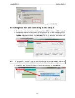
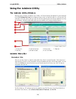
ioAdmin supports four viewing options for the navigation panel. If you select
Sort by Active OPC server
, the
ioLogik W5300 will appear in the
Active OPC
server group. Alternately, the same device will be shown under
the
LAN
group if you connect to the W5300 with Ethernet cables, instead of over the cellular network.
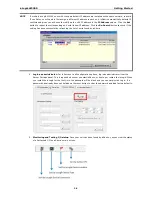
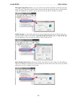
You can test each DO channel by opening the channel’s configuration window and selecting the
Digital Output
Test
tab.
After clicking the
Test
button, you can see how a channel’s status affects or is affected by the attached device.
For DO channels, you can set the on/off status to start and stop pulse output. For DI channels, you can monitor
the attached device’s on/off status, or monitor the counter.
You can now use ioAdmin to set up or configure your unit. Refer to Chapter 3 for additional information on using
ioAdmin.
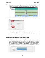
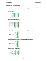
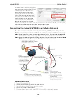
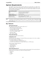
Configuring Digital I/O Channels
The ioLogik W5300 product family is equipped with different I/O types, including analog inputs, digital inputs,
digital outputs, relay outputs, and software configurable DIOs, offering great flexibility for connecting I/O
devices such as software configurable DIO channels. Before you connect I/O devices and sensors, you should
configure the DIO channels as DI or DO. The W5340 for example comes with 4 DI channels and 4 DO channels.
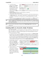
However, the user has the option of redefining the function of these channels. Each DIO channel is configured
to act as either a DI or DO channel, according to the
Power On Settings
. To switch between DI and DO
channel operation, select the desired mode in the
I/O Direction
field under
Power on Settings
. After clicking
Apply
, you will need to restart the ioLogik W5300 for the new setting to take effect.