


B
B-1
B
Printer and Serial Port
Connections
Introduction
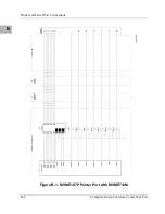
This appendix has connection diagrams for the printer port and the four
serial ports on the MVME1X7P. These ports are connected to external
devices through an MVME712M transition module.
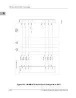
The configuration of the serial ports as Data Terminal Equipment (DTE)
or Data Circuit-terminating Equipment (DCE) is accomplished by jumpers
on the transition module. For more information, refer to the user’s manual
for the MVME712M.
Connection Diagrams
The following figures illustrate the connection diagrams for the
MVME712M transition module:
Figure
Number
Name
Figure B-1
MVME167P/177P Printer Port with MVME712M
Figure B-2
MVME167P/177P Serial Port 1 Configured as DCE
Figure B-3
MVME167P/177P Serial Port 2 Configured as DCE
Figure B-4
MVME167P/177P Serial Port 3 Configured as DCE
Figure B-5
MVME167P/177P Serial Port 4 Configured as DCE
Figure B-6
MVME167P/177P Serial Port 1 Configured as DTE
Figure B-7
MVME167P/177P Serial Port 2 Configured as DTE
Figure B-8
MVME167P/177P Serial Port 3 Configured as DTE
Figure B-9
MVME167P/177P Serial Port 4 Configured as DTE
Summary of Contents for MVME1X7P
Page 16: ...xvi ...
Page 18: ...xviii ...
Page 20: ...xx ...
Page 26: ...xxvi ...
Page 90: ...1 64 Computer Group Literature Center Web Site Programming Issues 1 ...
Page 248: ...3 50 Computer Group Literature Center Web Site PCCchip2 3 ...
Page 286: ...4 38 Computer Group Literature Center Web Site MCECC Functions 4 ...
Page 288: ...A 2 Computer Group Literature Center Web Site Summary of Changes A ...
Page 316: ...Index IN 14 Computer Group Literature Center Web Site I N D E X ...