


Programming Model
http://www.motorola.com/computer/literature
3-21
3
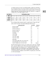
frequency is used for BCLK. To provide a 1 MHz clock to the tick timers,
the prescaler adjust register should be programmed based on the following
equation:
prescaler clock adjust register = 256 - BCLK (MHz)
For example, for operation at 20 MHz the prescaler value is $EC, at 25
MHz it is $E7, and at 33 MHz it is $DF.
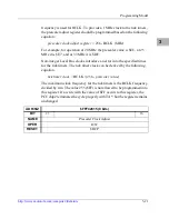
Non-integer Local Bus clocks introduce an error into the specified times
for the tick timers. The tick timer clock can be derived by the following
equation.
tick timer clock = BCLK / (256 - prescaler value)
The maximum clock frequency for the tick timers is the BCLK frequency
divided by two. The value 255 ($FF) is not allowed to be programmed into
this register. If a write with the value of $FF occurs to this register, the
PCCchip2 terminates the cycle properly with TA*, but the register remains
unchanged.
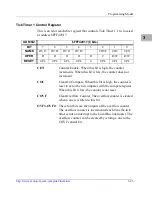
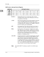
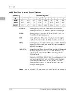
ADR/SIZ
$FFF42015 (8 bits)
BIT
23
. . .
16
NAME
Prescaler Clock Adjust
OPER
R/W
RESET
$DF P
Summary of Contents for MVME1X7P
Page 16: ...xvi ...
Page 18: ...xviii ...
Page 20: ...xx ...
Page 26: ...xxvi ...
Page 90: ...1 64 Computer Group Literature Center Web Site Programming Issues 1 ...
Page 248: ...3 50 Computer Group Literature Center Web Site PCCchip2 3 ...
Page 286: ...4 38 Computer Group Literature Center Web Site MCECC Functions 4 ...
Page 288: ...A 2 Computer Group Literature Center Web Site Summary of Changes A ...
Page 316: ...Index IN 14 Computer Group Literature Center Web Site I N D E X ...