


INSTRUCTION DESCRIPTIONS
MOTOROLA
INSTRUCTION SET DETAILS
A - 203
Example:
:
MPYR X1,Y0,A X1,X:(R0)+
Y0,Y:(R4)+N4
;X1
∗
Y0
➞
A,save X1 and Y0
:
Explanation of Example: Prior to execution, the 24-bit X1 register contains the value
$123123, the 24-bit Y0 register contains the value $456456, the 16-bit R0 address regis-
ter contains the value $1000, the 16-bit R4 address register contains the value $0100,
the 16-bit N4 address offset register contains the value $0023, the 24-bit X memory loca-
tion X:$1000 contains the value $000000, and the 24-bit Y memory location Y:$0100
contains the value $000000. The execution of the parallel move portion of the instruction,
X1,X:(R0)+ Y0,Y:(R4)+N4, moves the 24-bit value in the X1 register into the 24-bit X
memory location X:$1000 using the 16-bit R0 address register, moves the 24-bit value in
the Y0 register into the 24-bit Y memory location Y:$0100 using the 16-bit R4 address
register, updates the 16-bit value in the R0 address register, and updates the 16-bit R4
address register using the 16-bit N4 address offset register. The contents of the N4
address offset register are not affected.
Condition Codes:
S — Computed according to the definition in A.5 CONDITION CODE COMPUTATION
L — Set if data limiting has occurred during parallel move.
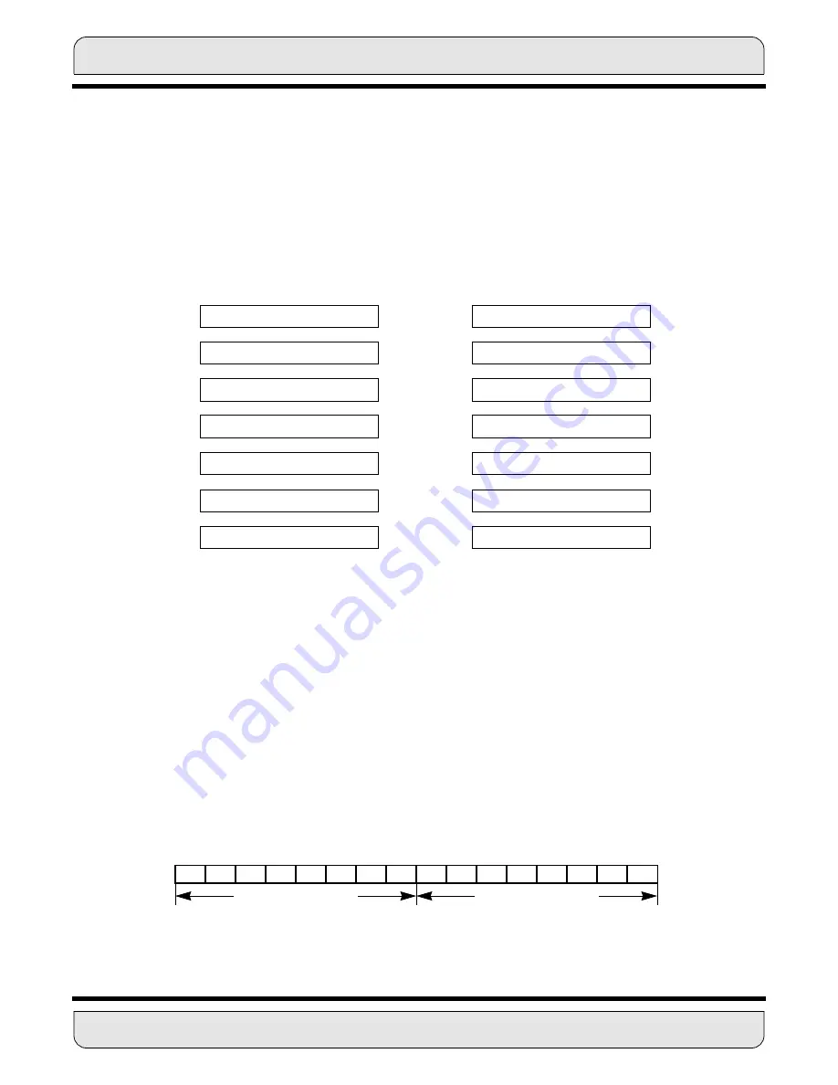
X: Y:
XY Memory Data Move
X: Y:
Before Execution
After Execution
X1
X1
$123123
$123123
Y0
Y0
$456456
$456456
R0
R0
$1000
$1001
R4
R4
$0100
$0123
X:$1000
X:$1000
$000000
$123123
N4
N4
$0023
$0023
Y:$0100
Y:$0100
$000000
$456456
MR
CCR
15
14
13
12
11
10
9
8
7
6
5
4
3
2
1
0
LF
DM
T
**
S1
S0
I1
I0
S
L
E
U
N
Z
V
C
Summary of Contents for DSP56K
Page 12: ...xii LIST of TABLES MOTOROLA List of Tables Continued Table Page Number Title Number ...
Page 13: ...MOTOROLA DSP56K FAMILY INTRODUCTION 1 1 SECTION 1 DSP56K FAMILY INTRODUCTION ...
Page 31: ...MOTOROLA DATA ARITHMETIC LOGIC UNIT 3 1 SECTION 3 DATA ARITHMETIC LOGIC UNIT ...
Page 50: ...DATA ALU SUMMARY 3 20 DATA ARITHMETIC LOGIC UNIT MOTOROLA ...
Page 51: ...MOTOROLA ADDRESS GENERATION UNIT 4 1 SECTION 4 ADDRESS GENERATION UNIT ...
Page 77: ...MOTOROLA PROGRAM CONTROL UNIT 5 1 SECTION 5 PROGRAM CONTROL UNIT ...
Page 124: ...INSTRUCTION GROUPS 6 30 INSTRUCTION SET INTRODUCTION MOTOROLA ...
Page 125: ...MOTOROLA PROCESSING STATES 7 1 SECTION 7 PROCESSING STATES STOP WAIT EXCEPTION NORMAL RESET ...
Page 167: ...STOP PROCESSING STATE MOTOROLA PROCESSING STATES 7 43 ...
Page 168: ...STOP PROCESSING STATE 7 44 PROCESSING STATES MOTOROLA ...
Page 169: ...MOTOROLA PORT A 8 1 SECTION 8 PORT A ...
Page 176: ...PORT A INTERFACE 8 8 PORT A MOTOROLA ...
Page 177: ...MOTOROLA PLL CLOCK OSCILLATOR 9 1 SECTION 9 PLL CLOCK OSCILLATOR x x d Φ VCO ...
Page 191: ...10 2 ON CHIP EMULATION OnCE MOTOROLA SECTION 10 ON CHIP EMULATION OnCE ...
Page 218: ...USING THE OnCE MOTOROLA ON CHIP EMULATION OnCE 10 29 ...
Page 604: ...INSTRUCTION ENCODING A 338 INSTRUCTION SET DETAILS MOTOROLA ...
Page 605: ...MOTOROLA BENCHMARK PROGRAMS B 1 APPENDIX B BENCHMARK PROGRAMS T T T T T P1 P3 P2 P4 T T T ...
Page 609: ...BENCHMARK PROGRAMS MOTOROLA BENCHMARK PROGRAMS B 5 ...
Page 611: ...BENCHMARK PROGRAMS MOTOROLA BENCHMARK PROGRAMS B 7 ...
Page 613: ...BENCHMARK PROGRAMS MOTOROLA BENCHMARK PROGRAMS B 9 ...
Page 615: ...BENCHMARK PROGRAMS MOTOROLA BENCHMARK PROGRAMS B 11 ...


