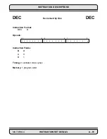
INSTRUCTION DESCRIPTIONS
A - 84
INSTRUCTION SET DETAILS
MOTOROLA
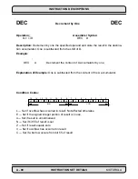
Example:
(4-Quadrant division, 24-bit signed quotient, 48-bit signed remainder)
ABS A A,B
;make dividend positive, copy A1 to B1
EOR X0,B B,X:$0
;save rem. sign in X:$0, quo. sign in N
AND #$FE,CCR
;clear carry bit C (quotient sign bit)
REP #$18
;form a 24-bit quotient
DIV X0,A
;form quotient in A0, remainder in A1
TFR A,B
;save quotient and remainder in B1,B0
JPL SAVEQUO
;go to SAVEQUO if quotient is positive
NEG B
;complement quotient if N bit set
SAVEQUO TFR X0,B B0,X1
;save quo. in X1, get signed divisor
ABS B
;get absolute value of signed divisor
ADD A,B
;restore remainder in B1
JCLR #23,X:$0,DONE
;go to DONE if remainder is positive
MOVE #$0,B0
;clear LS 24 bits of B
NEG B
;complement remainder if negative
DONE
. . . . . . .
Explanation of Example:
Prior to execution, the 56-bit A accumulator contains the 56-
bit, sign-extended fractional dividend D (D=$00.0E66D7:F2832C=0.112513535894635
approx.) and the 24-bit X0 register contains the 24-bit, signed fractional divisor S
(S=$123456=0.142222166061401). Since |D|<|S|, the execution of the previous divide
routine stores the correct 24-bit signed quotient in the 24-bit X1 register (A/
X0=0.79111111164093=$654321=X1). The partial remainder is restored by reversing
the last DIV operation and adding back the absolute value of the signed divisor in X0 to
the partial remainder in A1. This produces the correct LS 24 bits of the 48-bit signed
remained in the 24-bit B1 register. Note that the remainder is really a 48-bit value which
has 24 bits of precision. Thus, the correct 48-bit remainder is $000000:000100 which
equals 0.0000000000018190 approximately.
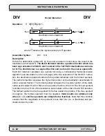
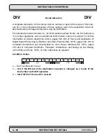
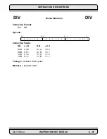
DIV
Divide Interation
DIV
Before Execution
After Execution
A
A
$00:0E66D7:F2832C
X0
X0
$123456
$123456
$FF:EDCCAA:654321
X1
X1
$000000
$654321
B
B
$00:000000:000000
$00:000100:654321
Summary of Contents for DSP56K
Page 12: ...xii LIST of TABLES MOTOROLA List of Tables Continued Table Page Number Title Number ...
Page 13: ...MOTOROLA DSP56K FAMILY INTRODUCTION 1 1 SECTION 1 DSP56K FAMILY INTRODUCTION ...
Page 31: ...MOTOROLA DATA ARITHMETIC LOGIC UNIT 3 1 SECTION 3 DATA ARITHMETIC LOGIC UNIT ...
Page 50: ...DATA ALU SUMMARY 3 20 DATA ARITHMETIC LOGIC UNIT MOTOROLA ...
Page 51: ...MOTOROLA ADDRESS GENERATION UNIT 4 1 SECTION 4 ADDRESS GENERATION UNIT ...
Page 77: ...MOTOROLA PROGRAM CONTROL UNIT 5 1 SECTION 5 PROGRAM CONTROL UNIT ...
Page 124: ...INSTRUCTION GROUPS 6 30 INSTRUCTION SET INTRODUCTION MOTOROLA ...
Page 125: ...MOTOROLA PROCESSING STATES 7 1 SECTION 7 PROCESSING STATES STOP WAIT EXCEPTION NORMAL RESET ...
Page 167: ...STOP PROCESSING STATE MOTOROLA PROCESSING STATES 7 43 ...
Page 168: ...STOP PROCESSING STATE 7 44 PROCESSING STATES MOTOROLA ...
Page 169: ...MOTOROLA PORT A 8 1 SECTION 8 PORT A ...
Page 176: ...PORT A INTERFACE 8 8 PORT A MOTOROLA ...
Page 177: ...MOTOROLA PLL CLOCK OSCILLATOR 9 1 SECTION 9 PLL CLOCK OSCILLATOR x x d Φ VCO ...
Page 191: ...10 2 ON CHIP EMULATION OnCE MOTOROLA SECTION 10 ON CHIP EMULATION OnCE ...
Page 218: ...USING THE OnCE MOTOROLA ON CHIP EMULATION OnCE 10 29 ...
Page 604: ...INSTRUCTION ENCODING A 338 INSTRUCTION SET DETAILS MOTOROLA ...
Page 605: ...MOTOROLA BENCHMARK PROGRAMS B 1 APPENDIX B BENCHMARK PROGRAMS T T T T T P1 P3 P2 P4 T T T ...
Page 609: ...BENCHMARK PROGRAMS MOTOROLA BENCHMARK PROGRAMS B 5 ...
Page 611: ...BENCHMARK PROGRAMS MOTOROLA BENCHMARK PROGRAMS B 7 ...
Page 613: ...BENCHMARK PROGRAMS MOTOROLA BENCHMARK PROGRAMS B 9 ...
Page 615: ...BENCHMARK PROGRAMS MOTOROLA BENCHMARK PROGRAMS B 11 ...


