INSTRUCTION DESCRIPTIONS
A - 150
INSTRUCTION SET DETAILS
MOTOROLA
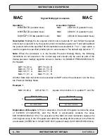
Operation:
Assembler Syntax:
D
±
S1
∗
S2
➞
D (parallel move)
MAC
(
±
)S1,S2,D (parallel move)
D
±
S1
∗
S2
➞
D (parallel move)
MAC
(
±
)S2,S1,D (parallel move)
D
±
(S1
∗
2
-n
)
➞
D (no parallel move)
MAC
(
±
)S,#n,D (no parallel move)
Description: Multiply the two signed 24-bit source operands S1 and S2 (or the signed
24-bit source operand S by the positive 24-bit immediate operand 2
-n
) and add/subtract
the product to/from the specified 56-bit destination accumulator D. The “–” sign option is
used to negate the specified product prior to accumulation. The default sign option is “+”.
Note: When the processor is in the Double Precision Multiply Mode, the following
instructions do not execute in the normal way and should only be used as part of the
double precision multiply algorithm shown in Section 3.4 DOUBLE PRECISION MULTI-
PLY MODE:
MPY Y0, X0, A
MPY Y0, X0, B
MAC X1, Y0, A
MAC X1, Y0, B
MAC X0, Y1, A
MAC X0, Y1, B
MAC Y1, X1, A
MAC Y1, X1, B
All other Data ALU instructions are executed as NOP’s when the processor is in the Dou-
ble Precision Multiply Mode.
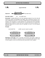
Example 1:
:
MAC X0,X0,A
X:(R2)+N2,Y1
;square X0 and store in A, update Y1 and R2
:
Explanation of Example 1: Prior to execution, the 24-bit X0 register contains the value
of $123456 (0.142222166), and the 56-bit A accumulator contains the value
$00:100000:000000 (0.125). The execution of the MAC X0,X0,A instruction squares the
24-bit signed value in the X0 register and adds the resulting 48-bit product to the 56-bit A
accumulator (X0
∗
X0+lA=0.145227144519197 approximately= $00:1296CD:9619C8=A).
MAC
Signed Multiply-Accumulate
MAC
Before Execution
After Execution
X0
X0
$123456
A
A
$00:100000:00000
$00:1296CD:9619C8
$123456
Summary of Contents for DSP56K
Page 12: ...xii LIST of TABLES MOTOROLA List of Tables Continued Table Page Number Title Number ...
Page 13: ...MOTOROLA DSP56K FAMILY INTRODUCTION 1 1 SECTION 1 DSP56K FAMILY INTRODUCTION ...
Page 31: ...MOTOROLA DATA ARITHMETIC LOGIC UNIT 3 1 SECTION 3 DATA ARITHMETIC LOGIC UNIT ...
Page 50: ...DATA ALU SUMMARY 3 20 DATA ARITHMETIC LOGIC UNIT MOTOROLA ...
Page 51: ...MOTOROLA ADDRESS GENERATION UNIT 4 1 SECTION 4 ADDRESS GENERATION UNIT ...
Page 77: ...MOTOROLA PROGRAM CONTROL UNIT 5 1 SECTION 5 PROGRAM CONTROL UNIT ...
Page 124: ...INSTRUCTION GROUPS 6 30 INSTRUCTION SET INTRODUCTION MOTOROLA ...
Page 125: ...MOTOROLA PROCESSING STATES 7 1 SECTION 7 PROCESSING STATES STOP WAIT EXCEPTION NORMAL RESET ...
Page 167: ...STOP PROCESSING STATE MOTOROLA PROCESSING STATES 7 43 ...
Page 168: ...STOP PROCESSING STATE 7 44 PROCESSING STATES MOTOROLA ...
Page 169: ...MOTOROLA PORT A 8 1 SECTION 8 PORT A ...
Page 176: ...PORT A INTERFACE 8 8 PORT A MOTOROLA ...
Page 177: ...MOTOROLA PLL CLOCK OSCILLATOR 9 1 SECTION 9 PLL CLOCK OSCILLATOR x x d Φ VCO ...
Page 191: ...10 2 ON CHIP EMULATION OnCE MOTOROLA SECTION 10 ON CHIP EMULATION OnCE ...
Page 218: ...USING THE OnCE MOTOROLA ON CHIP EMULATION OnCE 10 29 ...
Page 604: ...INSTRUCTION ENCODING A 338 INSTRUCTION SET DETAILS MOTOROLA ...
Page 605: ...MOTOROLA BENCHMARK PROGRAMS B 1 APPENDIX B BENCHMARK PROGRAMS T T T T T P1 P3 P2 P4 T T T ...
Page 609: ...BENCHMARK PROGRAMS MOTOROLA BENCHMARK PROGRAMS B 5 ...
Page 611: ...BENCHMARK PROGRAMS MOTOROLA BENCHMARK PROGRAMS B 7 ...
Page 613: ...BENCHMARK PROGRAMS MOTOROLA BENCHMARK PROGRAMS B 9 ...
Page 615: ...BENCHMARK PROGRAMS MOTOROLA BENCHMARK PROGRAMS B 11 ...


