


INSTRUCTION DESCRIPTIONS
A - 78
INSTRUCTION SET DETAILS
MOTOROLA
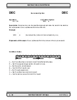
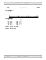
Operation:
Assembler Syntax:
If cc, then enter the debug mode
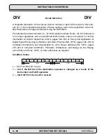
DEBUGcc
Description: If the specified condition is true, enter the debug mode and wait for OnCE
commands. If the specified condition is false, continue with the next instruction.
The term “cc” may specify the following conditions:
“cc” Mnemonic
Condition
CC (HS)
— carry clear (higher or same)
C=0
CS (LO)
— carry set (lower)
C=1
EC
— extension clear
E=0
EQ
— equal
Z=1
ES
— extension set
E=1
GE
— greater than or equal
N
⊕
V=0
GT
— greater than
Z+(N
⊕
V)=0
LC
— limit clear
L=0
LE
— less than or equal
Z+(N
⊕
V)=1
LS
— limit set
L=1
LT
— less than
N
⊕
V=1
MI
— minus
N=1
NE
— not equal
Z=0
NR
— normalized
Z+(U
•
E)=1
PL —
plus
N=0
NN
— not normalized
Z+(U
•
E)=0
where
U denotes the logical complement of U,
+
denotes the logical OR operator,
•
denotes the logical AND operator, and
⊕
denotes the logical Exclusive OR operator
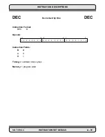
Condition Codes:
The condition codes are not affected by this instruction.
DEBUGcc
Enter Debug Mode Conditionally
DEBUGcc
MR
CCR
15
14
13
12
11
10
9
8
7
6
5
4
3
2
1
0
LF
DM
T
**
S1
S0
I1
I0
S
L
E
U
N
Z
V
C
Summary of Contents for DSP56K
Page 12: ...xii LIST of TABLES MOTOROLA List of Tables Continued Table Page Number Title Number ...
Page 13: ...MOTOROLA DSP56K FAMILY INTRODUCTION 1 1 SECTION 1 DSP56K FAMILY INTRODUCTION ...
Page 31: ...MOTOROLA DATA ARITHMETIC LOGIC UNIT 3 1 SECTION 3 DATA ARITHMETIC LOGIC UNIT ...
Page 50: ...DATA ALU SUMMARY 3 20 DATA ARITHMETIC LOGIC UNIT MOTOROLA ...
Page 51: ...MOTOROLA ADDRESS GENERATION UNIT 4 1 SECTION 4 ADDRESS GENERATION UNIT ...
Page 77: ...MOTOROLA PROGRAM CONTROL UNIT 5 1 SECTION 5 PROGRAM CONTROL UNIT ...
Page 124: ...INSTRUCTION GROUPS 6 30 INSTRUCTION SET INTRODUCTION MOTOROLA ...
Page 125: ...MOTOROLA PROCESSING STATES 7 1 SECTION 7 PROCESSING STATES STOP WAIT EXCEPTION NORMAL RESET ...
Page 167: ...STOP PROCESSING STATE MOTOROLA PROCESSING STATES 7 43 ...
Page 168: ...STOP PROCESSING STATE 7 44 PROCESSING STATES MOTOROLA ...
Page 169: ...MOTOROLA PORT A 8 1 SECTION 8 PORT A ...
Page 176: ...PORT A INTERFACE 8 8 PORT A MOTOROLA ...
Page 177: ...MOTOROLA PLL CLOCK OSCILLATOR 9 1 SECTION 9 PLL CLOCK OSCILLATOR x x d Φ VCO ...
Page 191: ...10 2 ON CHIP EMULATION OnCE MOTOROLA SECTION 10 ON CHIP EMULATION OnCE ...
Page 218: ...USING THE OnCE MOTOROLA ON CHIP EMULATION OnCE 10 29 ...
Page 604: ...INSTRUCTION ENCODING A 338 INSTRUCTION SET DETAILS MOTOROLA ...
Page 605: ...MOTOROLA BENCHMARK PROGRAMS B 1 APPENDIX B BENCHMARK PROGRAMS T T T T T P1 P3 P2 P4 T T T ...
Page 609: ...BENCHMARK PROGRAMS MOTOROLA BENCHMARK PROGRAMS B 5 ...
Page 611: ...BENCHMARK PROGRAMS MOTOROLA BENCHMARK PROGRAMS B 7 ...
Page 613: ...BENCHMARK PROGRAMS MOTOROLA BENCHMARK PROGRAMS B 9 ...
Page 615: ...BENCHMARK PROGRAMS MOTOROLA BENCHMARK PROGRAMS B 11 ...


