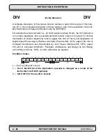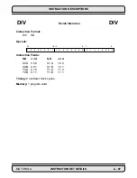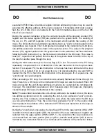
INSTRUCTION DESCRIPTIONS
A - 74
INSTRUCTION SET DETAILS
MOTOROLA
Operation:
Assembler Syntax:
|S2| – |S1|(parallel move)
CMPM
S1, S2 (parallel move)
Description: Subtract the absolute value (magnitude) of the source one operand, S1,
from the absolute value of the source two accumulator, S2, and update the condition
code register. The result of the subtraction operation is not stored.
Note: This instruction subtracts 56-bit operands. When a word is specified as S1, it is
sign extended and zero filled to form a valid 56-bit operand. For the carry to be set cor-
rectly as a result of the subtraction, S2 must be properly sign extended. S2 can be
improperly sign extended by writing A1 or B1 explicitly prior to executing the compare so
that A2 or B2, respectively, may not represent the correct sign extension. This note par-
ticularly applies to the case where it is extended to compare 24-bit operands such as X0
with A1.
Example:
:
CMPM X1,A
BA,L:–(R4)
;comp. Y0 and B, save X0, Y1
:
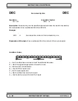
Explanation of Example: Prior to execution, the 56-bit A accumulator contains the
value $00:000006:000000, and the 24-bit X1 register contains the value $FFFFF7. The
execution of the CMPM X1,A instruction automatically appends the 24-bit value in the X1
register with 24 LS zeros, sign extends the resulting 48-bit long word to 56 bits, takes the
absolute value of the resulting 56-bit number, subtracts the result from the absolute
value of the contents of the 56-bit A accumulator, and updates the condition code regis-
ter.
CMPM
Compare Magnitude
CMPM
Before Execution
After Execution
A
A
$00:000006:000000
X1
X1
$FFFFF7
$FFFFF7
$00:000006:000000
SR
SR
$0300
$0319
Summary of Contents for DSP56K
Page 12: ...xii LIST of TABLES MOTOROLA List of Tables Continued Table Page Number Title Number ...
Page 13: ...MOTOROLA DSP56K FAMILY INTRODUCTION 1 1 SECTION 1 DSP56K FAMILY INTRODUCTION ...
Page 31: ...MOTOROLA DATA ARITHMETIC LOGIC UNIT 3 1 SECTION 3 DATA ARITHMETIC LOGIC UNIT ...
Page 50: ...DATA ALU SUMMARY 3 20 DATA ARITHMETIC LOGIC UNIT MOTOROLA ...
Page 51: ...MOTOROLA ADDRESS GENERATION UNIT 4 1 SECTION 4 ADDRESS GENERATION UNIT ...
Page 77: ...MOTOROLA PROGRAM CONTROL UNIT 5 1 SECTION 5 PROGRAM CONTROL UNIT ...
Page 124: ...INSTRUCTION GROUPS 6 30 INSTRUCTION SET INTRODUCTION MOTOROLA ...
Page 125: ...MOTOROLA PROCESSING STATES 7 1 SECTION 7 PROCESSING STATES STOP WAIT EXCEPTION NORMAL RESET ...
Page 167: ...STOP PROCESSING STATE MOTOROLA PROCESSING STATES 7 43 ...
Page 168: ...STOP PROCESSING STATE 7 44 PROCESSING STATES MOTOROLA ...
Page 169: ...MOTOROLA PORT A 8 1 SECTION 8 PORT A ...
Page 176: ...PORT A INTERFACE 8 8 PORT A MOTOROLA ...
Page 177: ...MOTOROLA PLL CLOCK OSCILLATOR 9 1 SECTION 9 PLL CLOCK OSCILLATOR x x d Φ VCO ...
Page 191: ...10 2 ON CHIP EMULATION OnCE MOTOROLA SECTION 10 ON CHIP EMULATION OnCE ...
Page 218: ...USING THE OnCE MOTOROLA ON CHIP EMULATION OnCE 10 29 ...
Page 604: ...INSTRUCTION ENCODING A 338 INSTRUCTION SET DETAILS MOTOROLA ...
Page 605: ...MOTOROLA BENCHMARK PROGRAMS B 1 APPENDIX B BENCHMARK PROGRAMS T T T T T P1 P3 P2 P4 T T T ...
Page 609: ...BENCHMARK PROGRAMS MOTOROLA BENCHMARK PROGRAMS B 5 ...
Page 611: ...BENCHMARK PROGRAMS MOTOROLA BENCHMARK PROGRAMS B 7 ...
Page 613: ...BENCHMARK PROGRAMS MOTOROLA BENCHMARK PROGRAMS B 9 ...
Page 615: ...BENCHMARK PROGRAMS MOTOROLA BENCHMARK PROGRAMS B 11 ...


