INSTRUCTION DESCRIPTIONS
A - 88
INSTRUCTION SET DETAILS
MOTOROLA
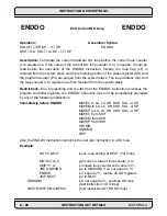
Operation:
Assembler Syntax:
SP+1
➞
SP;LA
➞
SSH;LC
➞
SSL;X:ea
➞
LC
DO
X:ea,expr
SP+1
➞
SP;PC
➞
SSH;SR
➞
SSL;expr –1
➞
LA
1
➞
LF
SP+1
➞
SP;LA
➞
SSH;LC
➞
SSL;X:aa
➞
LC
DO
X:aa,expr
SP+1
➞
SP;PC
➞
SSH;SR
➞
SSL;expr –1
➞
LA
1
➞
LF
SP+1
➞
SP;LA
➞
SSH;LC
➞
SSL;Y:ea
➞
LC
DO
Y:ea,expr
SP+1
➞
SP;PC
➞
SSH;SR
➞
SSL;expr –1
➞
LA
1
➞
LF
SP+1
➞
SP;LA
➞
SSH;LC
➞
SSL;Y:aa
➞
LC
DO
Y:aa,expr
SP+1
➞
SP;PC
➞
SSH;SR
➞
SSL;expr –1
➞
LA
1
➞
LF
SP+1
➞
SP;LA
➞
SSH;LC
➞
SSL;#xxx
➞
LC
DO
#xxx,expr
SP+1
➞
SP;PC
➞
SSH;SR
➞
SSL;expr –1
➞
LA
1
➞
LF
SP+1
➞
SP;LA
➞
SSH;LC
➞
SSL;S
➞
LC
DO
S,expr
SP+1
➞
SP;PC
➞
SSH;SR
➞
SSL;expr –1
➞
LA
1
➞
LF
End of Loop:
SSL(LF)
➞
SR;SP–1
➞
SP
SSH
➞
LA;SSL
➞
LC;SP – 1
➞
SP
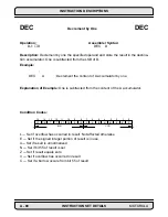
Description: Begin a hardware DO loop that is to be repeated the number of times spec-
ified in the instruction’s source operand and whose range of execution is terminated by
the destination operand (previously shown as “expr”). No overhead other than the execu-
tion of this DO instruction is required to set up this loop. DO loops can be nested and the
loop count can be passed as a parameter.
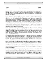
During the first instruction cycle, the current contents of the loop address (LA) and the
loop counter (LC) registers are pushed onto the system stack. The DO instruction’s
source operand is then loaded into the loop counter (LC) register. The LC register con-
tains the remaining number of times the DO loop will be executed and can be accessed
from inside the DO loop subject to certain restrictions. If LC equals zero, the DO loop is
DO
Start Hardware Loop
DO
Summary of Contents for DSP56K
Page 12: ...xii LIST of TABLES MOTOROLA List of Tables Continued Table Page Number Title Number ...
Page 13: ...MOTOROLA DSP56K FAMILY INTRODUCTION 1 1 SECTION 1 DSP56K FAMILY INTRODUCTION ...
Page 31: ...MOTOROLA DATA ARITHMETIC LOGIC UNIT 3 1 SECTION 3 DATA ARITHMETIC LOGIC UNIT ...
Page 50: ...DATA ALU SUMMARY 3 20 DATA ARITHMETIC LOGIC UNIT MOTOROLA ...
Page 51: ...MOTOROLA ADDRESS GENERATION UNIT 4 1 SECTION 4 ADDRESS GENERATION UNIT ...
Page 77: ...MOTOROLA PROGRAM CONTROL UNIT 5 1 SECTION 5 PROGRAM CONTROL UNIT ...
Page 124: ...INSTRUCTION GROUPS 6 30 INSTRUCTION SET INTRODUCTION MOTOROLA ...
Page 125: ...MOTOROLA PROCESSING STATES 7 1 SECTION 7 PROCESSING STATES STOP WAIT EXCEPTION NORMAL RESET ...
Page 167: ...STOP PROCESSING STATE MOTOROLA PROCESSING STATES 7 43 ...
Page 168: ...STOP PROCESSING STATE 7 44 PROCESSING STATES MOTOROLA ...
Page 169: ...MOTOROLA PORT A 8 1 SECTION 8 PORT A ...
Page 176: ...PORT A INTERFACE 8 8 PORT A MOTOROLA ...
Page 177: ...MOTOROLA PLL CLOCK OSCILLATOR 9 1 SECTION 9 PLL CLOCK OSCILLATOR x x d Φ VCO ...
Page 191: ...10 2 ON CHIP EMULATION OnCE MOTOROLA SECTION 10 ON CHIP EMULATION OnCE ...
Page 218: ...USING THE OnCE MOTOROLA ON CHIP EMULATION OnCE 10 29 ...
Page 604: ...INSTRUCTION ENCODING A 338 INSTRUCTION SET DETAILS MOTOROLA ...
Page 605: ...MOTOROLA BENCHMARK PROGRAMS B 1 APPENDIX B BENCHMARK PROGRAMS T T T T T P1 P3 P2 P4 T T T ...
Page 609: ...BENCHMARK PROGRAMS MOTOROLA BENCHMARK PROGRAMS B 5 ...
Page 611: ...BENCHMARK PROGRAMS MOTOROLA BENCHMARK PROGRAMS B 7 ...
Page 613: ...BENCHMARK PROGRAMS MOTOROLA BENCHMARK PROGRAMS B 9 ...
Page 615: ...BENCHMARK PROGRAMS MOTOROLA BENCHMARK PROGRAMS B 11 ...


