background image

MSD Single-Axis System Operation Manual AC-AC Servo Drive

ID no.: CA65642-001 06/2018

moog

21

Electrical installation

Electrical installation

4.1  Notes for installation

It is imperative you pay attention to the following warnings and safety instructions prior to 
and during installation.

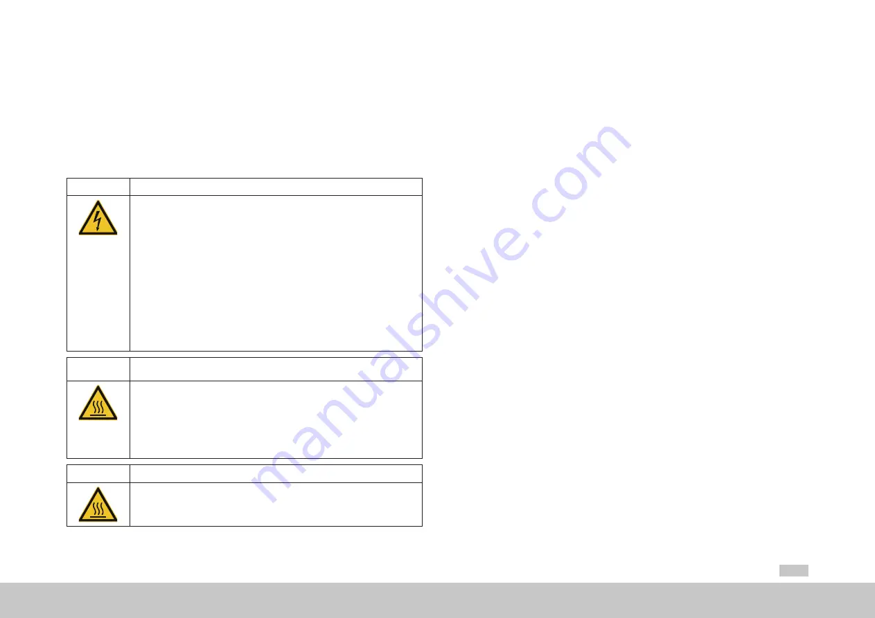
DANGER!

Risk of injury due to electrical power!

• 

Carelessness will result in serious injuries or death.

Never make or disconnect electrical connections while they are electrically live! Always 

disconnect the power before working on the device. Even 10 min. (Size 1 to Size 4) / 30 min.  

(Size 5 to Size 7) after switching off the mains supply, dangerously high voltages of ≥50 V 

may still be present (capacitor charge). 

So check that electrical power is not 

present!

Work on the device must only be carried out after the DC link voltage has dropped below a 

residual voltage of 50 V (on Size 1 to Size 6A to be measured on the terminals X11/L+ and L-, 

on Size 7 on the terminals X11/ZK- and X11/ZK+).
Any existing additional DC link connections as well as all motor connections are to be checked 

in relation to each other and in relation to earth to ensure they are not carrying any electrical 

power. If necessary, all cable connections are to be discharged using suitable means.
A dangerous voltage may be present at the device, even if the device does not emit any visual 

or audible signals/indications (e.g. with mains voltage applied to terminal X11 and missing 

control 24 V on X9/X10 and X44)!

WARNING

!

Risk of injury due to hot surfaces on the device (heat sink)!

• 

Carelessness may result in serious burns.

The device and especially the heat sink heat up significantly during operation and can reach 

temperatures of up to +100 °C (+212 °C). Prior to starting work, make sure the device has 

cooled down.
On touching there is a risk of burns to the skin. For this reason provide protection against 

touching.
During mounting maintain an appropriate distance to neighbouring assemblies.

WARNING

!

Risk of injury due to hot coolant!

• 

Carelessness may result in serious burns.

In operation the coolant reaches high temperatures. Prior to starting work, make sure the 

coolant has cooled down. 

4.2  Effective EMC installation

4.2.1 

Cable type


y

Use only shielded mains, motor and signal cables. For all shielded connections, use cables with 
double copper braiding with 60 to 70 % coverage.


y

If it is necessary to lay very large cable cross-sections, instead of shielded cables it is also 
possible to lay separate individually shielded wires. Please contact our application specialists on 
the Helpline.

4.2.2 

Routing of cables

You should take into account the following points on laying the cables:


y

Route mains, motor and signal cables separated from one another. Maintain a distance of at 
least 200 mm (7.87 in).


y

For smaller distances use separators for shielding; fasten the separators directly and 
conductively to the backing plate.


y

Route the cables close to ground potential. On the usage of cable ducts made of plastic, the 
cable ducts must be fastened directly to the backing plates or the frame. Open space must not 
be spanned, as otherwise the cables could act like antennae.


y

Route motor cables without interruptions (e.g. not via terminals) and lay them by the shortest 
route out of the switch cabinet. 


y

If a motor contactor or a motor choke is used, the component should be positioned directly at the 
servo drive and the shielding on the motor cable should not be stripped back too far.


y

Avoid unnecessary cable lengths and "loops of spare cable". 


y

Route long cables in places not be susceptible to interference. Otherwise coupling points may be 
created. 


y

Twist wires for the same electrical circuit.


y

Ideally, route the signal cables separated from encoder cables.


y

All signal cables should be combined and routed away upward.


y

Avoid extending cables via terminals.

Summary of Contents for G305-170

Page 1: ...moog AC AC Servo Drive Single axis System 4 A to 450 A MSD Servo Drive Operation Manual...

Page 2: ...tice The content of our documentation was compiled with the greatest care and attention and based on the latest information available to us We should nevertheless point out that this document cannot a...

Page 3: ...s 22 4 2 7 Shielding measures 23 4 2 8 External components 23 4 3 Overview of the connections Size 1 to Size 4 24 4 3 1 Connection diagram 25 4 4 Overview of the connections Size 5 to Size 6A 26 4 4 1...

Page 4: ...5 Connection for high resolution encoders 42 4 15 Motor connection 43 4 15 1 Motor connection for servo motors 43 4 15 2 Ready made motor cable 44 4 15 3 Switching in the motor cable 45 4 16 Braking r...

Page 5: ...ty Size 5 to Size 6A liquid cooling 69 A 1 6 Current carrying capacity Size 7 liquid cooling 71 A 2 Technical data MSD Servo Drive 72 A 2 1 G392 004A to G392 016 air cooling 72 A 2 2 G392 020 to G392...

Page 6: ...6 MSD Single Axis System Operation Manual AC AC Servo Drive ID no CA65642 001 06 2018 moog...

Page 7: ...le standards technical data CA65642 001 PDF MSD Servo Drive DC AC Servo Drive Multi Axis System Operation Manual Safety mechanical installation electrical installation commissioning diagnostics STO op...

Page 8: ...article designation is given in the following order code You will find the complete order code with all values in the MSD Servo Drive Ordering Catalog G392 Rated current Supply voltage Option 1 Commu...

Page 9: ...dispose of individual parts depending on their characteristics and existing national regulations e g as y y Electrical waste y y Plastic y y Metal Or engage a certified disposal organisation with scr...

Page 10: ...e if you have any technical queries relating to project planning or commissioning your device Address Moog GmbH Hanns Klemm Stra e 28 D 71034 B blingen Phone 49 7031 622 0 Fax 49 7031 622 100 E mail d...

Page 11: ...citor charge So check that electrical power is not present See also the warning label on the front panel on the device Rotating parts Automatically starting drives Hot components and surfaces 3 Protec...

Page 12: ...ER Risk of injury due to rotating parts on the motor Carelessness will result in serious injuries or death Follow safety instructions and warnings in this document Pay attention to special safety inst...

Page 13: ...4 1 Repair Only have repairs undertaken by authorised repair shops Unauthorised repairs could lead to death injury or damage see previous chapter The warranty provided by Moog will be rendered void 2...

Page 14: ...14 Safety AC AC Single Axis System Operation Manual MSD Servo Drive ID no CA65642 001 06 2018 moog 2 8 Declaration of conformity 2 8 1 MSD Servo Drive AC AC Size 1 to Size 7...

Page 15: ...to Size 7 y y Maximum pollution degree 2 according to IEC EN 60664 1 y y The servo drives must not be installed in areas where they would be permanently exposed to vibration You will find more informa...

Page 16: ...00 H1 355 382 5 600 H2 38 5 15 20 All dimensions in mm 1 Without terminals connectors and shield plates 2 If necessary take into account larger bending radii for connection cables Table 3 2 Dimensions...

Page 17: ...anual AC AC Servo Drive ID no CA65642 001 06 2018 moog 17 Mechanical installation B H1 H H2 T A D C1 C Size 1 A D C1 D C Size 2 Size 6A Figure 3 2 Dimensional drawing housing with air cooling schemati...

Page 18: ...ore for pipe fitting E 2 F 2 150 180 G 2 270 300 500 All dimensions in mm 1 Without terminals connectors and shield plates 2 If necessary take into account larger bending radii for connection cables 3...

Page 19: ...Mechanical installation B T T1 H1 H H2 H3 A2 A A1 D C C1 D D1 S Figure 3 4 Dimensional drawing housing with liquid cooling schematic depiction for Size 3 to Size 6A H1 C A A T T1 H A1 A2 H3 S D1 D B H...

Page 20: ...nt escaping and to make it possible to disconnect and connect in the filled state 1 2 3 4 5 Key 1 Liquid connection with 3 8 inch female thread 2 Self sealing quick release connection with 3 8 inch ma...

Page 21: ...this reason provide protection against touching During mounting maintain an appropriate distance to neighbouring assemblies WARNING Risk of injury due to hot coolant Carelessness may result in serious...

Page 22: ...with the EMC product standard IEC EN 61800 3 for the general availability residential C1 additional external mains filters are available for devices with an internal mains filter Size 1 to Size 5 4 2...

Page 23: ...e 4 3 Shield connection y y Do not strip back too far the shield y y Shields are not allowed to be used to carry power e g as a substitute for the N or PE conductor y y The shielding effect can be imp...

Page 24: ...In the following you will find the layout with the corresponding positions of the connectors and terminals For improved clarity we have added an abbreviation to the designation for the connectors and...

Page 25: ...11 X10 X9 X2 X3 X4 X8 X7 X6 X5 X13 X12 Front Option 1 24 V DC Power supply for control electronic UV Communication Field buses Brake Brake Resolver Encoder e g additional encoder 1 2 1 2 Top side Bott...

Page 26: ...ors and terminals For improved clarity we have added an abbreviation to the designation for the connectors and terminals X20 X8 X7 X6 D1 D2 T1 T2 X2 X3 X4 X5 X11 X9 X10 SW HW X12 PE L1 L2 L3 RB RB W V...

Page 27: ...ide Bottom side X11 X10 X9 X2 X3 X4 X20 X8 X7 X6 X5 X12 Service interface 24 V bridge only for MSD Servo Drive AC AC Size 5 Figure 4 8 Connection diagram Size 5 to Size 6A NOTE There is a special aspe...

Page 28: ...on the left shows the corresponding positions of connectors and terminals For improved clarity we have added an abbreviation to the designation for the connectors and terminals X11 X45 D1 D2 T1 T2 X2...

Page 29: ...triggering 24 V DC power supply for brake I 2 0 A IN Communication Field buses Brake Brake e g additional encoder Encoder Resolver 1 2 3 4 5 6 7 Top side Bottom side X11 X2 X3 X4 X44 X8 X7 X6 X5 X12...

Page 30: ...a star configuration and with a large area connection to the PE rail main earth in the switch cabinet W1 V2 W2 U2 U1 V1 W1 V2 W2 U2 U1 V1 W1 V2 W2 U2 U1 V1 PE Figure 4 11 Star configuration layout for...

Page 31: ...trical isolation concept for Size 1 to Size 4 24V DC OSD03 Motor brake GND X20 1 X20 2 X20 3 Size 7 only Size 7 Size 5 and Size 6A X44 5 X44 6 X44 7 only for hardware versions 0 and 1 Up to hardware v...

Page 32: ...le Observe total power consumption 1 2 1 2 L1 L2 L3 D1 D2 1 2 1 2 Top side Top side Device 1 Device 2 X11 X9 X10 X11 X9 X10 Figure 4 14 Connection of control supply Size 1 to Size 6A NOTE Suitable mea...

Page 33: ...t present CAUTION Risk of injury or damage to the device due to incorrect residual current device Carelessness may result in injuries or damage If local regulations require the installation of an resi...

Page 34: ...2 9 4 1 3 x maximum 10 G392 006 4 4 6 3 3 x maximum 16 G392 008 6 0 8 5 3 x maximum 20 G392 012 9 1 13 0 3 x maximum 25 G392 016 G395 016 12 0 16 2 3 x maximum 32 G392 020 G395 020 15 0 20 1 3 x maxi...

Page 35: ...g setpoint 2 24 V DC against DGND 24 V UH 3 4 5 6 10 15 16 17 9 23 24 22 RSH Diagnosis STO 12 11 1 2 14 13 E A GND Relay Digital2 RB RB ZK ZK Brake resistor U V W 6 8 Triggering of motor brake ISD03 I...

Page 36: ...a defined DC link voltage the contact on the internal relay on terminal X44 3 4 is closed The auxiliary contactor K3 closes and switches on the main contactor K1 The precharging contactor K2 is opene...

Page 37: ...1 20 19 18 17 16 15 14 13 12 11 10 9 8 7 6 5 4 3 2 1 X4 ISA0 ISA0 ISA1 ISA1 X4 3 X4 4 X4 5 X4 6 UIN 10 V DC Resolution 12 bits RIN approx 101 k Terminal scan cycle in the IP mode 125 s otherwise 1 ms...

Page 38: ...le damage in the event of a short circuit 24 V GND but device may briefly shut down Imax 80 mA per pin with self resetting circuit breaker polyswitch Yes Digital ground DGND X4 1 X4 13 Reference groun...

Page 39: ...e IIN 2 A 24 V 1 GND 2 VL1 3 VL2 4 24 V 5 OSD03 6 GND 7 Table 4 13 Specification of the terminal connections X44 Size 7 4 10 Specification USB interface The service and diagnostic interface X2 is desi...

Page 40: ...ignment 4 14 1 Encoder connection for servo motors Please use the ready made motor and encoder cables from Moog to connect the servo motors 4 14 2 Allocation of motor encoder cable to the servo drive...

Page 41: ...mm 3 93 in 90 mm 3 54 in Temperature range 40 to 85 C 40 to 185 F 35 to 80 C 31 to 176 F 40 to 85 C 40 to 185 F Table 4 15 Technical data encoder cables CO8335 013 yyy1 CA58876 002 yyy1 CA58877 002 y...

Page 42: ...sensor cable is it ensured that the encoder is supplied with the correct voltage The sensor cable must always be connected Select the cable type specified by the motor or encoder manufacturer During...

Page 43: ...s to reduce interference emissions CAUTION Damage to the device due to incorrect insulation of the motor winding Carelessness can cause damage to the motor device The motor temperature sensor must in...

Page 44: ...ure range 40 bis 125 C 40 to 275 F TBD 50 bis 90 C 58 to 194 F TBD TBD Wiring Connector pin Wiring Connector pin Wiring Connector pin Wiring Connector pin Wiring Connector pin Wiring 2 U 2 U U U U U U...

Page 45: ...ink If the voltage exceeds the switch on threshold the internal brake chopper transistor is activated and the regenerated power is converted into heat by means of a braking resistor Device Mains volta...

Page 46: ...can be used for a one off braking action The permissible energy WIBr can be taken from the following table Device Technology Rated resistance RBR Peak braking power PPBr Pulse energy WIBr K1 G392 004...

Page 47: ...1 Br T PBr DBr dt P T P 0 1 1 1 K I I P N eff DBr T Br DBr PBr dt P P T 0 T P P T DBr PBr BrSum The maximum total on time of the braking resistor over a specified cycle time T with calculated continuo...

Page 48: ...ing of the ext braking resistor The external braking resistor must be monitored by the controller The temperature of the braking resistor is monitored by a temperature sensor Klixon In the event of ov...

Page 49: ...each temperatures of up to 100 C 212 F On touching there is a risk of burns to the skin For this reason provide protection against touching 5 2 Initial commissioning Once the MSD Servo Drive has been...

Page 50: ...ettings for the related interface see Installation Manual Moog DriveAdministrator 5 5 2 3 Configuring parameters 4 The commissioning wizard in Moog DriveAdministrator 5 is provided for making the sett...

Page 51: ...er switching on the AC mains supply D1 D2 Action Reaction Explanation Switch on the AC mains supply Controller ready power stage ready control deactivated Device is ready to switch on Table 5 2 Displa...

Page 52: ...ed to the drive immediately after the motor control has started and can result in the unexpected acceleration of the drive Details for optimising the drive on your application can be found in the Moog...

Page 53: ...device status display Scroll through the menus sub menus Set values left segment display D1 The button T1 can be held pressed for any length of time because the display will only scroll through the me...

Page 54: ...displayed would represent the decimal value 16 Table 5 5 Meaning of display NOTE If no input is made via the buttons for 60 s the display switches back to the indication of the device status 5 4 3 Par...

Page 55: ...tting 192 168 39 5 Su b0 00 FF Subnet mask update byte 0 Setting for byte 0 of the subnet mask in hexadecimal format e g 00 in 255 255 255 0 b1 00 FF Subnet mask update byte 1 Setting for byte 1 of th...

Page 56: ...ion 1 2 Fb Ad 00 xx or Field bus address Setting for field bus address only if field bus option used otherwise indication The maximum value that can be programmed depends on the option Po 0 3 or Trans...

Page 57: ...tion extinguishes if function is inactive 2 The point flashes if the power stage is active Table 6 1 Device states 6 1 2 Error indication The specific error codes are indicated via the 7 segment displ...

Page 58: ...in the header for the MDA5 to open the Device status window Figure 6 1 Device status button in the header Use the Error history button to retrieve information on the last 20 errors that have occurred...

Page 59: ...tics Alarms Warnings details contains detailed information on an error or a warning that has occured 1 Double click in the project tree Alarms Warnings Details Figure 6 4 Parameter 31 Alarms Warnings...

Page 60: ...60 Diagnostics MSD Single Axis System Operation Manual AC AC Servo Drive ID no CA65642 001 06 2018 moog...

Page 61: ...nual AC AC Servo Drive ID no CA65642 001 06 2018 moog 61 Safe Torque Off STO 7 Safe Torque Off STO NOTE You will find all information on the STO function in the 24 language document Description of the...

Page 62: ...62 Safe Torque Off STO MSD Single Axis System Operation Manual AC AC Servo Drive ID no CA65642 001 06 2018 moog Space for your own notes...

Page 63: ...maximum permissible current carrying capacity of the servo drives also changes A 1 1 G392 004A air cooling 1 x 230 V AC Servo drive Switching frequency of the power stage Ambient temperature Rated cur...

Page 64: ...1 4 45 2 113 4 8 4 8 4 8 200 10 8 40 104 4 8 4 8 4 8 12 3 7 7 4 2 9 5 8 2 7 5 4 16 2 7 5 4 1 6 3 2 1 3 2 6 G392 006 Size 1 4 45 2 113 6 12 6 12 6 12 200 10 8 40 104 6 12 6 12 6 12 12 5 5 11 4 4 8 8 4...

Page 65: ...27 8 13 3 26 6 12 11 22 8 8 17 6 8 16 16 8 16 5 9 11 8 5 2 10 4 G392 020 Size 3 4 45 113 20 40 20 40 20 40 200 10 8 40 104 20 40 17 4 34 8 16 6 33 2 12 13 8 27 6 11 22 10 20 16 10 20 7 4 14 8 6 5 13 G...

Page 66: ...Hz Up to 5 Hz 5 Hz Aeff 0 Hz Up to 5 Hz 5 Hz Aeff 0 Hz Up to 5 Hz 5 Hz s G392 045 Size 5 4 45 113 45 90 90 42 83 84 41 81 82 200 3 10 3 8 40 104 45 90 90 42 83 84 41 81 82 12 45 90 90 42 83 84 41 81 8...

Page 67: ...81 153 162 200 30 8 40 104 90 134 180 83 124 166 81 121 162 200 12 90 107 144 83 99 133 81 95 130 160 16 72 86 115 67 80 107 65 77 104 160 G392 110 Size 6 4 45 113 110 170 220 102 157 204 99 153 198...

Page 68: ...f kHz C F Aeff 0 Hz to 5 Hz Aeff 0 Hz to 5 Hz Aeff 0 Hz to 5 Hz s G395 016 Size 3 4 45 113 16 32 16 32 16 32 200 10 8 40 104 16 32 13 9 27 8 13 3 26 6 12 11 22 8 8 17 6 8 16 16 8 16 5 9 11 8 5 2 10 4...

Page 69: ...nearly During inter mittent opera tion At rotating field frequency increas ing linearly During inter mittent opera tion kHz C F Aeff 0 Hz Up to 5 Hz 5 Hz Aeff 0 Hz Up to 5 Hz 5 Hz Aeff 0 Hz Up to 5 Hz...

Page 70: ...204 99 186 198 200 30 8 110 166 187 102 154 173 99 150 168 170 12 110 133 165 102 123 153 99 120 149 150 16 90 106 135 83 99 125 81 96 122 150 G395 143 Size 6 4 45 113 143 232 286 132 214 264 129 208...

Page 71: ...nt Aeff 2 At rotating field frequency in creasing linearly During inter mittent opera tion At rotating field frequency in creasing linearly During inter mittent opera tion At rotating field frequency...

Page 72: ...g the drive it is to be taken into account that the maximum output voltage reduces as a function of the active power Table A 9 Technical data G392 004A to G392 016 air cooling Designation Technical da...

Page 73: ...aken into account that the maximum output voltage reduces as a function of the active power 3 Connection of an ext braking resistor to devices with int braking resistor not permitted model G392 xxx xx...

Page 74: ...mum ohmic resistance of an externally installed braking resistor 12 10 8 5 6 5 1 Data referred to mains voltage 3 x 400 Veff and switching frequency of the power stage 8 kHz 2 When designing the drive...

Page 75: ...xxx xxx xx2 xx4 4 Cooling performance adequate also with optional internal braking resistor Table A 12 Technical data G395 016 to G395 070 liquid cooling Designation Technical data G395 016 G395 020...

Page 76: ...084 to G395 210 liquid cooling Designation Technical data G395 084 G395 110 G395 143 G395 170 G395 210 DC link Capacitance 900 F 2120 F 4240 F Brake chopper switch on threshold 820 V DC Minimum ohmic...

Page 77: ...also with optional internal braking resistor Table A 14 Technical data G395 250 to G395 450 liquid cooling Designation Technical data G395 250 G395 325 G395 450 Minimum ohmic resistance of an external...

Page 78: ...pply Housing variant Size Maximum starting current Continuous current Air cooling Size 1 to Size 4 6 A 2 A Size 5 7 A 2 5 A Size 6 to Size 6A 10 A 0 A 10 A 1 Liquid cooling Size 3 to Size 4 6 A 2 A Si...

Page 79: ...nly be maximum 40 2 The absolute humidity is limited to maximum 29 g m So the maximum values for temperature and relative atmospheric humidity stipulated in the table must not occur simultaneously 3 T...

Page 80: ...terminals 2 To comply with the standard mains chokes uK 4 up to 32 A uK 2 for 45 to 450 A must be used 3 Standard can only be met with an external filter no internal filter fitted 4 Also applies at a...

Page 81: ...to prevent condensation on the heat sink Cooler material Aluminium Table A 22 Requirements liquid cooling Size Size 3 Size 4 Size 5 Size 6A Size 7 Coolant pressure rated value maximum value 1 bar 2 b...

Page 82: ...82 MSD Single Axis System Operation Manual AC AC Servo Drive ID no CA65642 001 06 2018 moog...

Page 83: ...Capable for energy chains 41 Capacitor charging 33 48 Climatic conditions 79 Commissioning 39 40 49 50 51 Connection diagram 27 29 36 BG1 to BG4 25 Connections 20 28 30 37 51 78 BG1 to BG4 24 Etherne...

Page 84: ...O 12100 13 EN ISO 13849 15 79 ENPO 37 51 52 Environment 80 Ambient conditions 33 78 Ambient temperature 33 43 46 63 75 76 77 81 Environment class 33 34 Error Error code 57 Error number 54 57 Error ind...

Page 85: ...ystem 33 TT system 33 Mains filters 22 Measures for your safety 11 Mechanical conditions 79 Mechanical installation 15 Minimum clearance 16 18 Misuse 13 MMC card slot See also X1 Moog DriveAdministrat...

Page 86: ...estart 56 Restart inhibit 37 Rotating field frequency 63 72 73 74 75 76 77 Routing of cables 21 S Safety 11 Device safety 33 Safety extra low voltage 30 Safety function 49 51 61 78 Safety function 15...

Page 87: ...also Service interface USB interface X3 39 See also Service interface Ethernet interface X4 37 38 51 X5 41 43 51 See also Motor Motor temperature sensor X6 41 40 42 43 51 See also Resolver X7 41 40 4...

Page 88: ...88 MSD Single Axis System Operation Manual AC AC Servo Drive ID no CA65642 001 06 2018 moog...

Page 89: ...89 MSD Single Axis System Operation Manual AC AC Servo Drive ID no CA65642 001 06 2018 moog...

Page 90: ...6664 info india moog com service india moog com Russia 7 831 713 1811 Service 7 831 764 5540 info russia moog com service russia moog com Brazil 55 11 3572 0400 info brazil moog com service brazil mo...

Reviews: