34
Electrical installation
MSD Single-Axis System Operation Manual AC-AC Servo Drive
ID no.: CA65642-001 06/2018
moog
NOTE:
Please be aware that the MSD Servo Drive is not designed for the mains
quality inenvironment class 3 (IEC/EN 61000-2-4). Further measures are
essential to achieve this environment class! For further information please
consult your project engineer.
NOTE:
The minimum cross-section of the mains power cable depends on the local
regulations and conditions, as well as on the rated current of the servo drive.
CAUTION! Damage to the device due to incorrect operation!
•
Carelessness can cause damage to the device.
Only when the mains voltage has been pre-set in the device firmware and the device has been
restarted (if the mains voltage or switching frequency has been changed) may the mains power
supply for the supply for the power section be activated.
4.8.3
AC mains supply, Size 1 to Size 4
Servo drive
Device connected load
1)
[kVA]
Specified mains fuse,
utilisation class gG [A]
With mains choke (4 % u
K
)
Without mains choke
G392-004A
1.6
2.2
1 x maximum 16
G392-004
2.9
4.1
3 x maximum 10
G392-006
4.4
6.3
3 x maximum 16
G392-008
6.0
8.5
3 x maximum 20
G392-012
9.1
13.0
3 x maximum 25
G392-016
G395-016
12.0
16.2
3 x maximum 32
G392-020
G395-020
15.0
20.1
3 x maximum 40
G392-024
G395-024
18.2
24.7
3 x maximum 50
G392-032
G395-032
24.2
32.7
3 x maximum 63
1)
At 3 x 400 V mains voltage
Table 4.6 Connected load and mains fuse (Size 1to Size 4)
USB 1.1
ISD00
ISD01
ISD02
OSD02
Relay
ENPO (STO)
Motor
3
Option 2
Control
Service
interface
ISDSH (STO)
ISA00+
ISA00-
ISA01+
ISA01-
Analog setpoint 1
Analog setpoint 2
+24 V DC against
E/A-GND
+24 V (U
H
)
3
4
5
6
10
15
16
17
9
23
24
22
RSH
Diagnosis
STO
12
11
1
2,14
13
E/A-GND
Relay
Digital2
RB
L+
L-
Brake
resistor
U
V
W
6
8
Triggering of
motor brake
ISD03
ISD04
ISD05
18
19
20
ISD06
21
OSD01
8
Digital1
OSD00
7
Digital0
GND
OSD03
+
-
1
2
5
9
DC-link
OSD04
5432
1
10
987
6
15
14
13
12
11
DGND
DGND
43
21
98
76
~
+
-
D1, D2
T1, T2
Ethernet
L1
K1
L2
L3
FN
L1
L2
L3
Mains three-phase
L1
PE
PE
K1
N
FN
L1
N
Mains one-phase
X11
X11
X10
X9
X2
X3
X4
X8
X7
X6
X5
X13
X12
Front
Option 1
24 V DC Power supply
for control electronic (U
V
)
Communication
Field buses
Brake (+)
Brake (-)
(+)
Resolver
-
+
-
+
Encoder
e.g. additional
encoder
1
2
1
2
Top
side
Bottom side
Service
interface
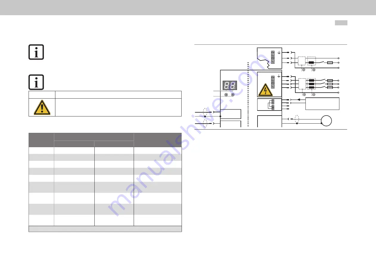
Figure 4.15 Connection example, control/mains supply for Size 1 to Size 4
Summary of Contents for G305-170
Page 1: ...moog AC AC Servo Drive Single axis System 4 A to 450 A MSD Servo Drive Operation Manual...
Page 6: ...6 MSD Single Axis System Operation Manual AC AC Servo Drive ID no CA65642 001 06 2018 moog...
Page 82: ...82 MSD Single Axis System Operation Manual AC AC Servo Drive ID no CA65642 001 06 2018 moog...
Page 88: ...88 MSD Single Axis System Operation Manual AC AC Servo Drive ID no CA65642 001 06 2018 moog...
Page 89: ...89 MSD Single Axis System Operation Manual AC AC Servo Drive ID no CA65642 001 06 2018 moog...


